
Logic State Indicator
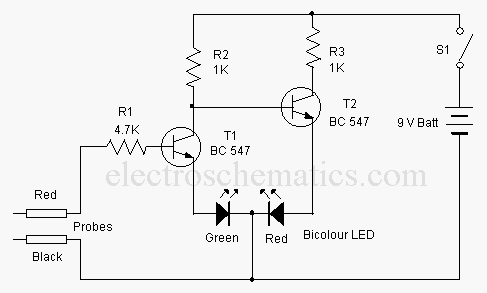
The circuit for the logic state indicator primarily consists of a digital IC output, a bicolor LED, and a current-limiting resistor. The digital IC output provides a binary signal, which can be either high (logic 1) or low (logic 0).
When the output from the IC is high, the current flows through the circuit, energizing the bicolor LED and causing it to emit green light. This is achieved by connecting the anode of the green segment of the bicolor LED to the output pin of the digital IC. The cathode of the green segment is connected to ground through a resistor, which limits the current flowing through the LED to a safe level, preventing damage.
Conversely, when the output is low, the bicolor LED does not light up, indicating a logic state of 0. The circuit can be powered using a standard voltage supply compatible with the digital IC, typically ranging from 3.3V to 5V, depending on the specifications of the IC used.
This simple yet effective logic state indicator is useful for troubleshooting digital circuits, allowing engineers and technicians to quickly ascertain the output state of an IC without the need for complex test equipment. The use of a bicolor LED enhances visibility and provides immediate feedback on the logic state.Here is a simple logic state indicator to test whether the output of digital IC is in logic 1 or 0. The Bicolor LED lights Green when the logic state is 1.. 🔗 External reference
Related Circuits
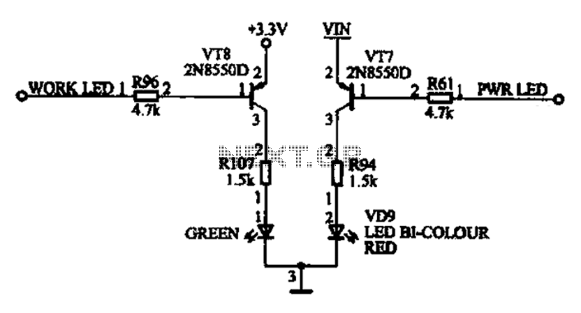
The ACER PM02 MP4 machine features a voltage status indicator circuit. When power is supplied, a red LED illuminates, indicating that the device is powered on. Upon entering operational mode, a green LED lights up. The voltage status indicator circuit...
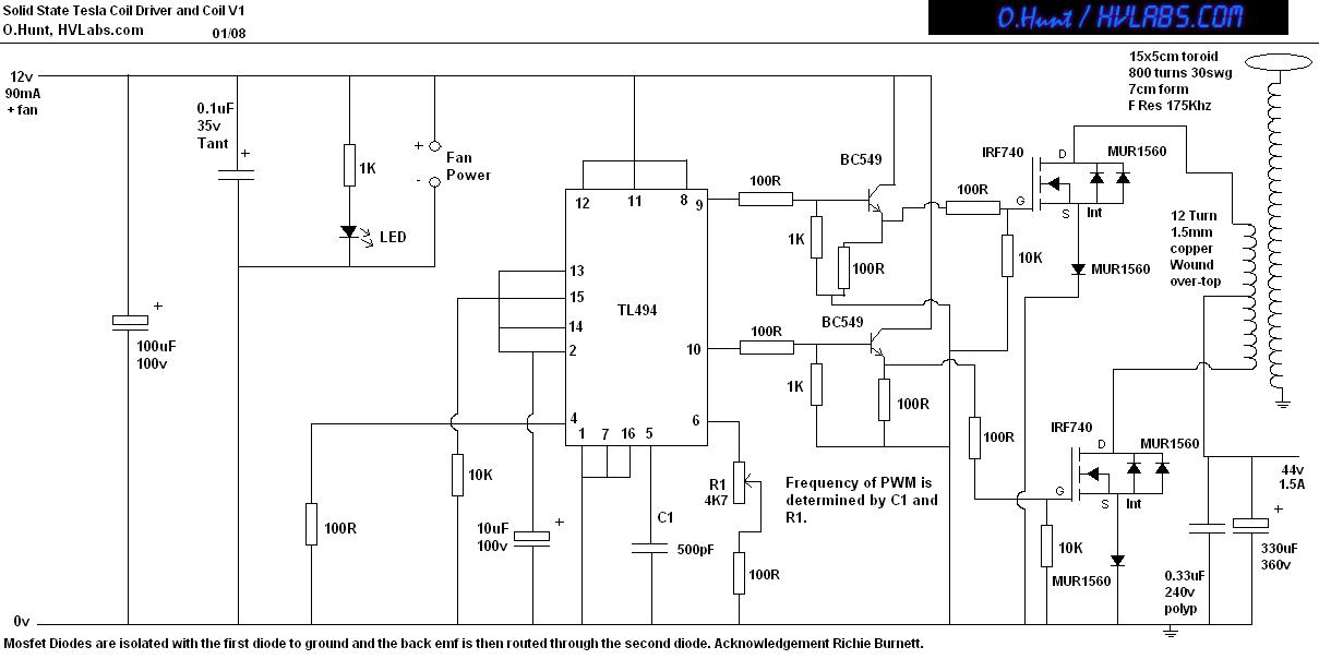
This is a solid-state version of a Tesla coil, replacing the spark gap with MOSFET transistors and utilizing a close-coupled primary coil without capacitors. The method of driving the primary coil varies among designs. After researching various works online,...
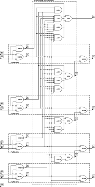
A 4-bit Carry Look Ahead Adder has 3 gate delays for all carry bits and 4 gate delays for all sum bits, whereas ripple adders have 7 and 8 gate delays, respectively. The 4-bit Carry Look Ahead Adder (CLA)...
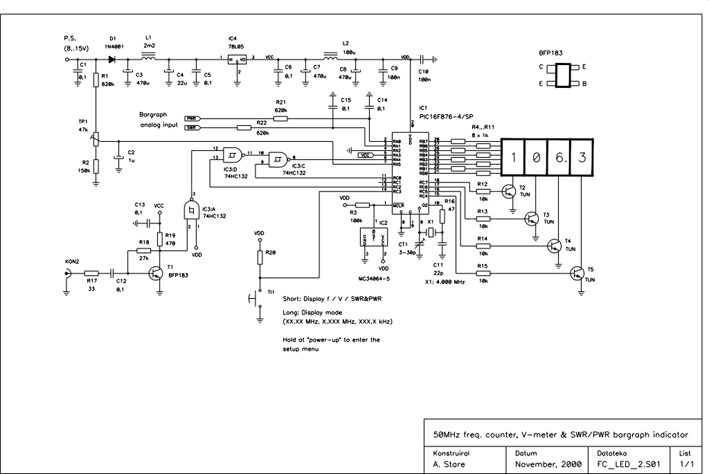
This device is an upgraded version of the PIC16C71 4-digit LED frequency counter and voltmeter. It eliminates several hard-to-find components from the previous model, which have been out of production for some time. The older PIC16C71 has been replaced...
When the water level is below the steel rods, there is no contact between the metal can and the rods, which are supported by a small insulated wooden board. The circuit built around IC1 draws no current, resulting in...
Solid State Relay Switch is a simple kit which will help you control (ON / OFF) a single high power circuit from a low power drive. Load - 24 to 240 VAC @ 500 W. Trigger voltage - 2...