
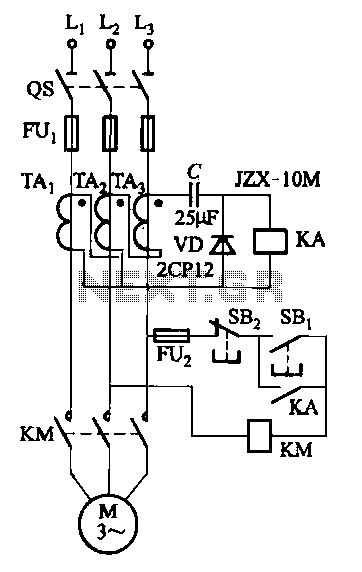
A third harmonic current phase protection circuits
The circuit illustrated in Figure 4-27 (b) incorporates a capacitor designed to improve the output current waveform of a DC voltage supply. By integrating this capacitor, the circuit effectively smooths out voltage fluctuations, resulting in a more stable and higher-quality DC output. This is particularly beneficial for applications involving larger capacity motors, which typically require a consistent power supply to operate efficiently.
The capacitor's role in this configuration is to store energy and release it as needed, thereby reducing ripple voltage and enhancing the overall performance of the motor. The selection of the capacitor's value is critical; it must be appropriately sized to match the load requirements of the motor. A larger capacitance will improve energy storage and discharge capabilities, leading to a more robust output current waveform.
In addition to the capacitor, other components such as inductors or additional filtering elements may be integrated into the circuit to further refine the output characteristics. Proper layout and design considerations, including the placement of components and the use of appropriate PCB techniques, are essential to minimize parasitic effects and ensure optimal performance.
Overall, the configuration presented in Figure 4-27 (b) is an effective solution for enhancing the performance of DC voltage supplies used in high-capacity motor applications, resulting in improved efficiency and reliability.Figure 4-27 (b) line than in Figure 4-27 (a) line more than a capacitor, to improve and increase the output current waveform DC voltage. Figure 4-27 (b) line shown can be used for larger capacity motor.
Related Circuits
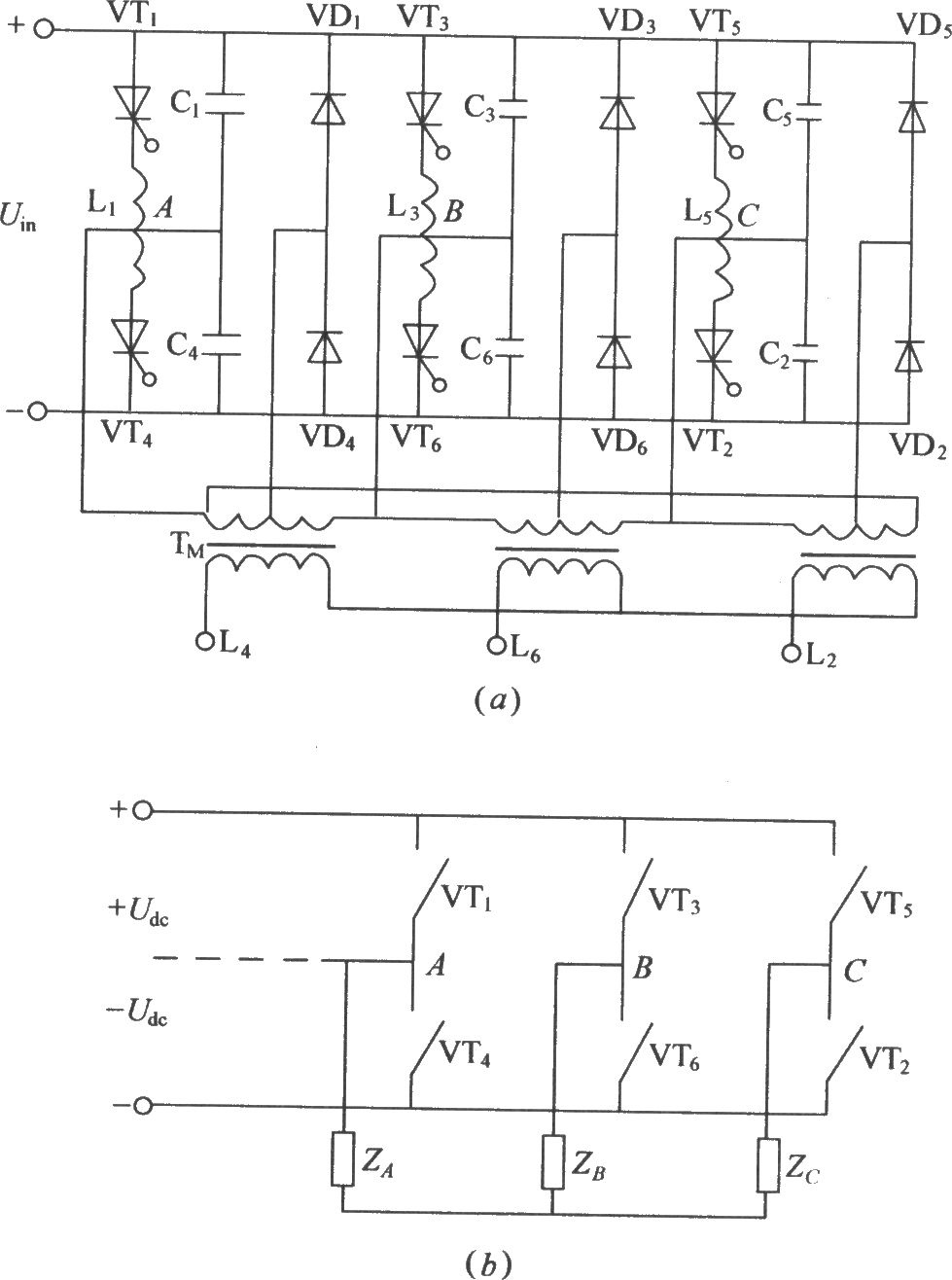
The figure illustrates a traditional three-phase bridge inverter circuit. Components VT1 to VT6 represent thyristors, while L1 to L6 are commutation reactors. Capacitors C1 to C6 serve as commutating capacitors, and the thyristor shut-off circuit is composed of two...
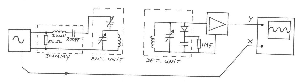
The frequency remains constant, oscillating between two predetermined values. On the oscilloscope display, a frequency spectrum is observed, showcasing the response curves of the two circuits. The input voltage of the receiver is 0.1 Volt peak-to-peak, while the voltage...

Controlling the speed of a three-phase AC motor is achieved by regulating the frequency of the power supply, as the motor operates in synchronization with the line frequency. A three-phase AC motor speed controller functions as a three-phase sine...
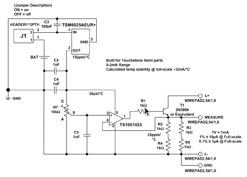
The MicroCC utilizes the Touchstone Semiconductor TSM6025 voltage reference, which serves as a direct replacement for the MAX6025, offering stability of better than 15 ppm/°C. The TSM6025 voltage reference is designed to provide a precise and stable output voltage, making...
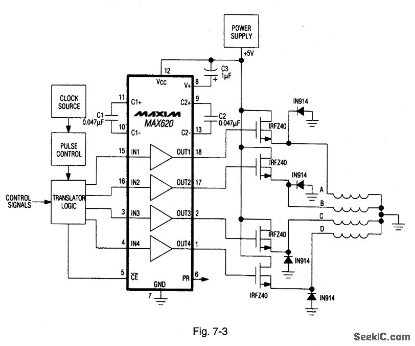
A MAX620 is connected to create a complete stepper motor drive system. TTL/CMOS signals from the logic network are converted to high-side levels that control four N-channel power MOSFETs, which supply current to each of the four phases of...

The composite pipe circuit limits the bulb cold current of the circuit. When the input signal is weak, a composite pipe circuit protection circuit is utilized, as illustrated in Figure 1. The composite pipe circuit functions as a protective mechanism...
Warning: include(partials/cookie-banner.php): Failed to open stream: Permission denied in /var/www/html/nextgr/view-circuit.php on line 713
Warning: include(): Failed opening 'partials/cookie-banner.php' for inclusion (include_path='.:/usr/share/php') in /var/www/html/nextgr/view-circuit.php on line 713