
Variable PSU
The variable power supply circuit employs the L200 voltage regulator, known for its versatility and reliability in providing stable output. The L200 device allows for both voltage and current regulation, making it suitable for various applications that require precise power delivery. The circuit design includes a mains transformer that steps down the high voltage from the AC mains to a lower voltage suitable for the L200 regulator. The transformer has a secondary winding rated at 12 volts and 2 amps, which is adequate for the power requirements of the circuit.
The control elements consist of two adjustable resistors (potentiometers). The first, a 10k ohm potentiometer, is responsible for setting the output voltage within a range of 3 to 15 volts. This range allows for flexibility in powering different electronic devices that may require varying voltage levels. The second potentiometer, with a resistance of 47 ohms, is used to limit the output current. This current limiting feature is critical for protecting both the power supply and the connected load from excessive current draw. The adjustable current limit can be set from a minimum of 10 mA to a maximum of 2 amps, ensuring that sensitive components are not damaged by overcurrent conditions.
When the load attempts to draw more current than the set limit, the power supply automatically reduces the output voltage to zero. This feature prevents potential damage to the power supply and the connected load, providing an essential safeguard in the design. The overall configuration of the circuit ensures that it operates efficiently and safely, making it a valuable tool for testing and powering a variety of electronic projects.A variable power supply with adjustable voltage and current outputs made with the L200 regulator. Using the versatile L200 voltage regulator, this power supply has independent voltage and current limits. The mains transformer has a 12volt, 2 amp rated secondary, the primary winding should equal the electricity supply in your country, which is 240V
here in the UK. The 10k control is adjusts voltage output from about 3 to 15 volts, and the 47 ohm control is the current limit. This is 10mA minimum and 2 amp maximum. Reaching the current limit will reduce the output voltage to zero. 🔗 External reference
Related Circuits
This simple variable power supply circuit has a low production cost and delivers an output voltage between 1.5 V and 15 V with a maximum current of 500 mA. This variable power supply circuit is designed to provide a versatile...
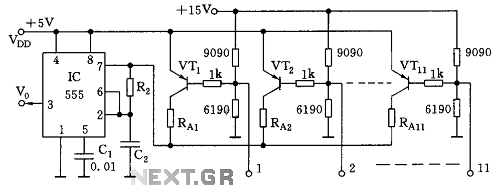
As illustrated in the figure, the base bias circuit for transistors VT1 to VT11 is designed to accept binary data, where a high level represents 1 and a low level represents 0. This configuration allows for 2048 combinations of...
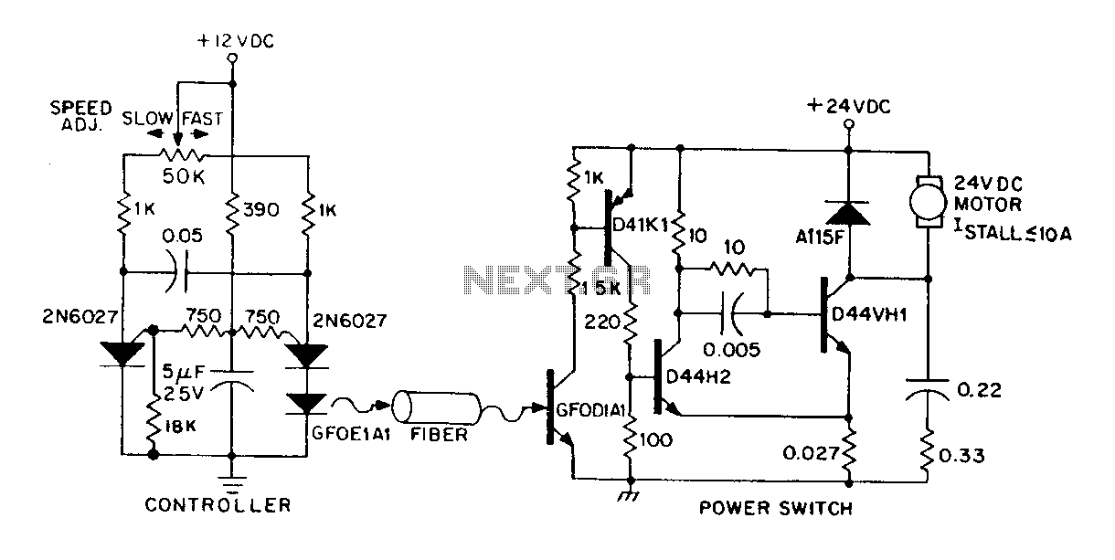
A DC power supply can be controlled through an optical fiber. The circuit includes a small DC motor (1/12 hp) that offers an isolated speed control channel. The control logic operates as an independent module, consuming 300 mW of...
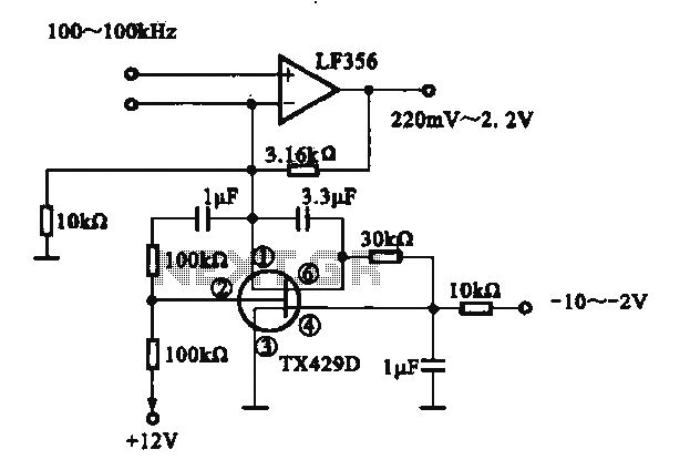
A variable gain amplifier is presented. This circuit adjusts the output signal amplitude based on the input signal. The core component is an operational amplifier configured with a negative feedback circuit. By varying the feedback amount, the gain of...
This LM338-based power supply can deliver approximately two outputs of 12 to 36 volts at 5 amps each (10 amps in version 2 of this power supply, which includes transistors to increase the current capacity). The design utilizes two...
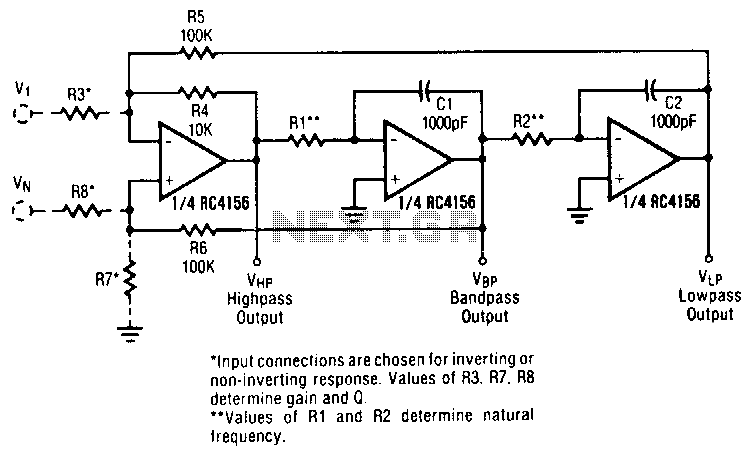
A generalized circuit diagram of the two-pole state-variable active filter is presented. This state-variable filter can be configured as either inverting or non-inverting and is capable of providing three simultaneous outputs: low-pass, bandpass, and high-pass. By incorporating an additional...