
Logic Pulser Circuit
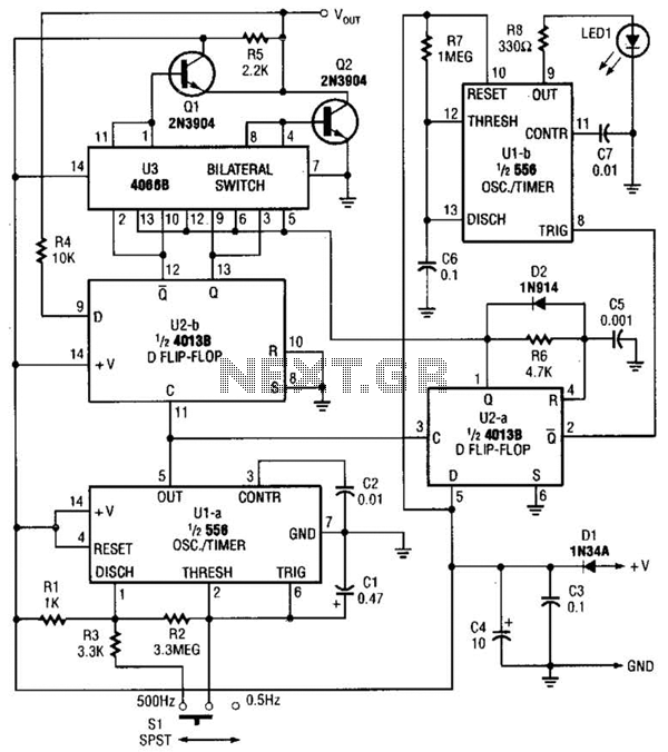
The logic pulser is a versatile electronic component designed to produce precise pulse signals at specified frequencies, namely 500 Hz and 0.5 Hz. This device is particularly useful in digital circuits where it is necessary to toggle the state of an input signal. The operation of the logic pulser is predicated on its ability to detect the current logic level of the connected input.
When the tip of the pulser is connected to an input that is already being driven either high (logic level '1') or low (logic level '0'), the pulser employs a sensing mechanism to determine the existing state of the signal. Upon detection of the current logic level, the pulser generates a pulse that briefly transitions the input to the opposite state. For instance, if the input is high, the pulser will output a low pulse, and conversely, if the input is low, it will output a high pulse.
This functionality is crucial in various applications, including digital signal processing, testing, and debugging of electronic circuits. The ability to generate a controlled pulse that can invert the state of a signal allows for effective manipulation of logic levels in a circuit, thereby facilitating the development and testing of digital systems.
The design of the logic pulser typically includes a timing circuit to regulate the frequency of the output pulses, a detection circuit to sense the input state, and a driver circuit to produce the necessary output signal. The integration of these components ensures reliable operation and precise timing, making the logic pulser an essential tool in the arsenal of electronic engineers and technicians. The logic pulser generates pulses at 500 Hz or 0.5 Hz. When the pulser`s.tip connects to an input that is already being driven high or low, the pulser senses thelogic state and automatically pulses the input briefly to the opposite state. 🔗 External reference
Related Circuits
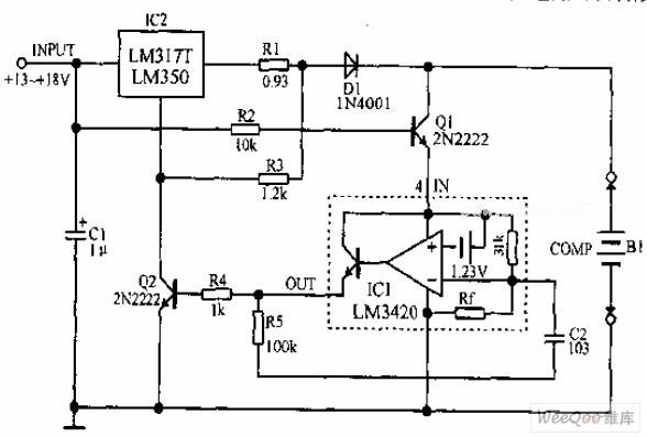
A lithium-ion battery charging circuit is illustrated above. Initially, when charging begins, if the battery voltage is below 8.4V, the output of IC1 is inactive. As a result, Q2 remains off, and the LM317 operates in constant current mode....
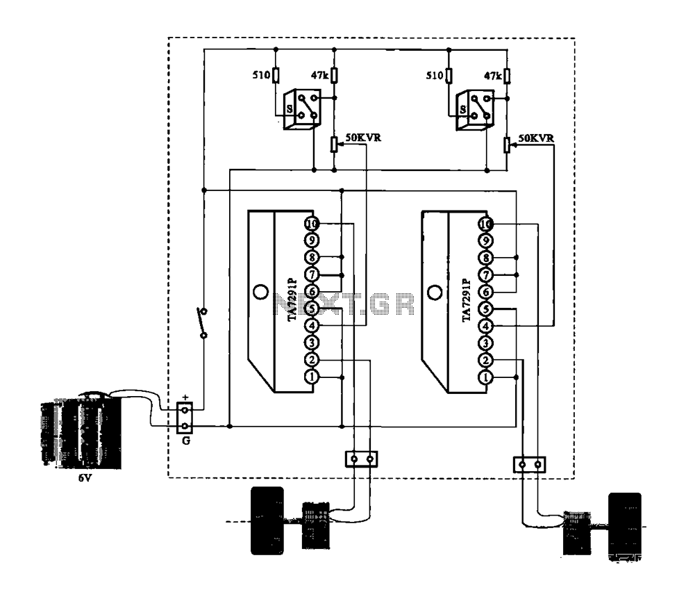
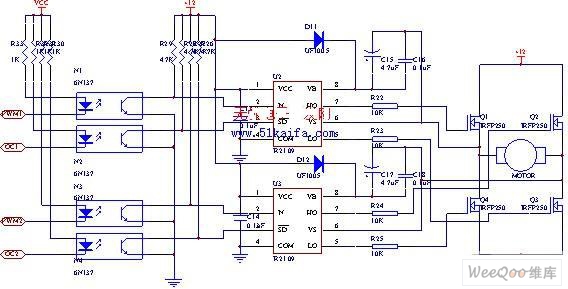
A dual motor drive circuit for automatic tracking consists of two motors that are part of a car structure, which operates based on the principles of a double motor drive system. The dual motor drive circuit is designed to facilitate...
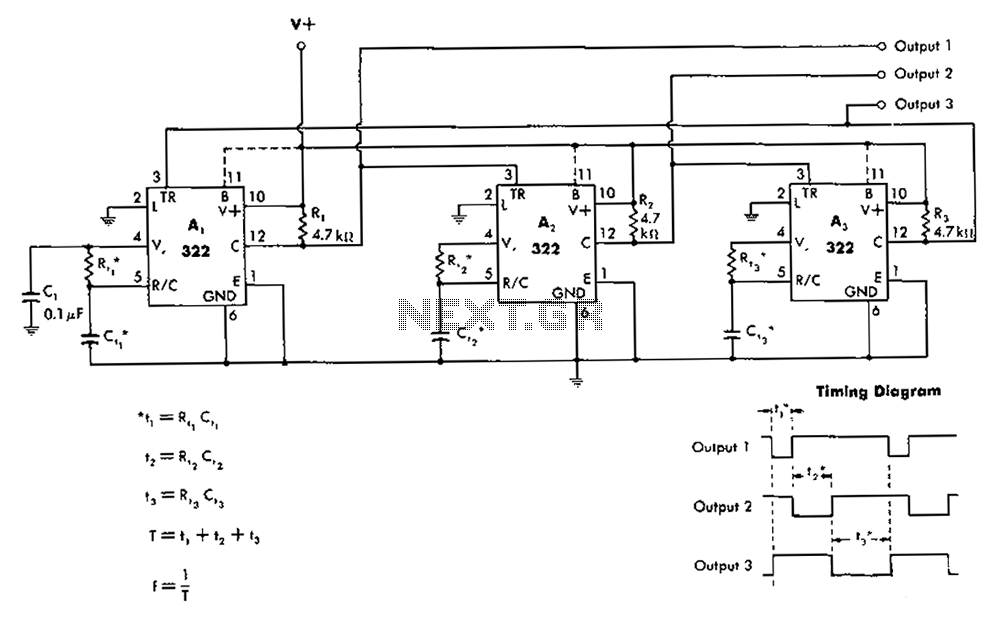
The 322 monostable multivibrator is configured in a cross-connected manner. When operating under non-steady state conditions with the oscillator Unicom, it generates a continuous timing cycle, as illustrated in the accompanying figure. T represents the total time period of...
The 555 timer on the right is configured as an alarm sound generator, while the second 555 timer on the left operates as a 1 Hz astable multivibrator. The output from the left timer modulates the frequency of the...
To achieve optimal audio reproduction across various listening levels, it is essential to adjust tone control settings to accommodate the known characteristics of human hearing. Human ear sensitivity changes in a non-linear fashion throughout the audible frequency range, as...
The drive circuit for the electromotor comprises a FET bridge circuit, a FET base drive circuit, a current sensor for the motor drive circuit, and a relay. The FET bridge circuit primarily consists of four high-power MOSFETs, which must...
Warning: include(partials/cookie-banner.php): Failed to open stream: Permission denied in /var/www/html/nextgr/view-circuit.php on line 713
Warning: include(): Failed opening 'partials/cookie-banner.php' for inclusion (include_path='.:/usr/share/php') in /var/www/html/nextgr/view-circuit.php on line 713