
Logic Tester
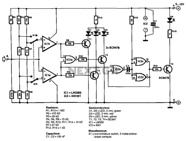
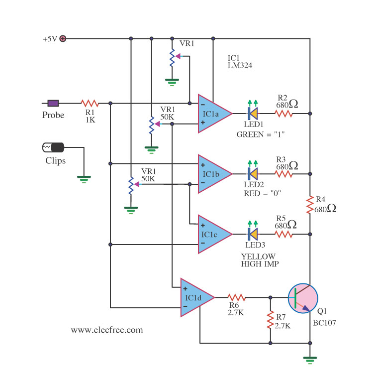
The circuit design utilizes two operational amplifiers configured as comparators to compare the input voltage (Ua) against predetermined reference voltages derived from voltage dividers. The use of separate dividers for each comparator allows for distinct threshold levels, making the circuit versatile for different applications. The TTL comparators operate with specific reference voltages that are set using resistors R3, R4, and R5, while the CMOS comparators utilize R6, R7, and R8 to establish their respective thresholds.
The output signals from the comparators are fed into driver stages, which control the illumination of LEDs indicating the comparison results. The green LED (D1) illuminates when the input voltage exceeds the reference voltage of IC1B, signaling a "high" condition, while the red LED (D2) indicates a "low" condition from IC1A when the input voltage is below its reference. The NOR gate (IC2A) monitors the output states of both comparators and activates a yellow LED (D3) when both outputs are low, indicating an undefined state.
The circuit also incorporates a monostable multivibrator configuration using the remaining gates in IC2. This configuration allows for a pulse to be lengthened, providing a visual indication via the yellow LED (D4) that remains lit for a defined duration after an input pulse is detected. The time constant determined by C2 and the resistor R13 ensures that even brief pulses are adequately processed, enhancing the reliability of the circuit's response to input changes.
In terms of power requirements, the circuit is designed to operate within a supply voltage range of 5 to 15 V, making it adaptable to various power sources. The current consumption is modest, drawing approximately 15 mA at the lower voltage limit, which is suitable for battery-operated applications. The high input impedance of approximately 330 kΩ ensures minimal loading on the signal source, making the circuit effective for testing and measurement applications. The input consists of two comparators that operate with different reference voltages supplied by separate potential dividers. Divider R3/R4/R5 provides a voltage of about 40% of the supply voltage, Ucc, to pin 6 of IC1B and one of about 16% of Ucc to pin 3 of UC1A. When Ucc = 5 V, these voltages are exactly the thresholds (0.8 and 2.0 V) of the TTL comparators. Similarly, divider R6/R7/R8 provides voltages of 23% of Ucc and 73% of Ucc to pin 3 of IC1A and pin 6 of IC1B respectively; these levels correspond to the standard threshold for CMOS comparators.
The voltage to be measured Ua, is applied to pin 5 of IC1B and pin 2 of IC1A and compared with the respective reference. The output of comparator IC1B goes high when Ua exceeds the reference, whereas the output of IC1A goes high when Ua lies below the voltage at pin 3.
The comparators are followed by driver stages, Tl and T2, for the LED display (Dl for "high" and D2 for " "low"") and also NOR gate IC2A that switches on T3 when the output of both comparators is low, that is, when it is undefined. This state is indicated by D3. The remaining three gates in IC2 form a monostable. During quiescent operation, Ucc is present at the input of inverter IC2C. The output of the inverter is then low, T4 is off and D4 is out. Pin 4 of IC2B is also high, but this state changes when a pulse arrives at pin 5. The output of IC2B then goes low, C2 discharges, the inverter toggles, T4 is switched on, and D4 lights.
This state is unstable, however, because C2 recharges via R13. Although the pulse at pin 5 might be very short, the time constant ffi3/C2 lengthens it to about 100 ms. The supply voltage can lie between 5 and 15 V. At 5 V, the circuit draws a current of about 15 mA. The input impedance of the tester is of the order of 330kohm. Resistors: R1, R13 = 1 R2 = 470 KOhm R3 = 39 k R4, R6, R8=15kfi R5, R9, R10, R11, R14 = 10 KOhmhm R7 = 27 k R12, R15 = 1 KOhmhm Capacitors: C1, C2= 100 nF Semiconductors: D1, D2 = LED, 3 mm, green D3 = LED, 3 mm, red D4 = LED, 3 mm, yellow T1, T2, T3, T4 = BC847 IC1 = LM358 102 = 4001 Miscellaneous: S1 = sub-miniature switch, 2 make-before-break contacts
🔗 External reference
Related Circuits
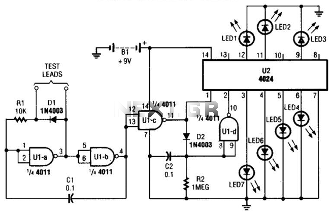
By observing the frequency at which a specific LED flashes, it is possible to estimate the resistance value. The circuit comprises two integrated circuits (ICs): a 4011 CMOS quad 2-input NAND gate (U1) and a 4024 binary counter (U2),...
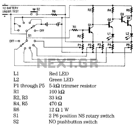
The battery tester utilizes four transistors and two LEDs to indicate the status of any battery being tested. Transistors Q3 and Q4 are configured in a Darlington arrangement, providing extremely high gain. LED L2 illuminates when a small positive...
This is a very simple circuit that can be used to test whether a pot is dry or not. When the two probes are inserted in wet soil, then the resistance between the sensors are low. The base of...

This device functions as a convenient tool for testing infrared (IR) remote control transmitters used with televisions, VCRs, and similar devices. The IR signals emitted from a remote control are detected by the IR sensor module within the tester,...
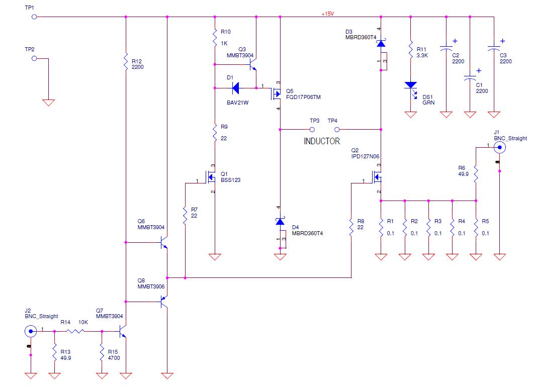
Yes, it does charge the inductor again. Diodes are beneficial as they do not charge the inductor back but dissipate a significant amount of instantaneous power due to the forward voltage drop. One approach would be to monitor the...
A logic probe is a useful tool for checking digital circuits. It functions similarly to a meter, which is employed to measure power in electrical circuits. A logic probe is an essential diagnostic instrument in digital electronics, designed to analyze...
Warning: include(partials/cookie-banner.php): Failed to open stream: Permission denied in /var/www/html/nextgr/view-circuit.php on line 713
Warning: include(): Failed opening 'partials/cookie-banner.php' for inclusion (include_path='.:/usr/share/php') in /var/www/html/nextgr/view-circuit.php on line 713