
Long Period SCR Timer
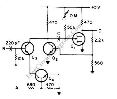
The SCR timer circuit operates by utilizing a silicon-controlled rectifier (SCR) to control the activation of a buzzer based on a time delay determined by the combination of resistor R1 and capacitor C1. When power is applied to the circuit, capacitor C1 begins to charge through resistor R1. The charging time of C1 is governed by the RC time constant, which is calculated as the product of R1 and C1.
Once the voltage across C1 reaches a predetermined threshold, it triggers the gate of transistor Q1, which is configured as a field-effect transistor (FET). The conduction of Q1 allows current to flow to the gate of SCR1, turning it on. This action activates the buzzer, producing an audible sound to indicate the completion of the timing cycle.
The choice of a FET for Q1 is significant as it allows for a much higher RC time constant compared to a standard bipolar junction transistor (BJT). This characteristic enables the circuit to achieve longer time delays, making it suitable for applications requiring extensive timing ranges. The overall design is simple yet effective, allowing for easy adjustments of the timing interval by varying the values of R1 and C1.
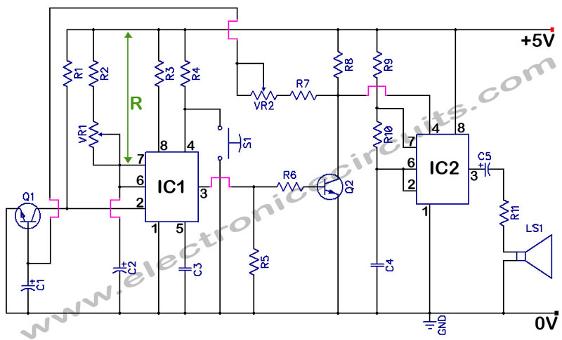
In summary, this SCR timer circuit exemplifies a practical application of SCR technology in timing applications, with the ability to deliver long delays and a straightforward operational mechanism. The schematic diagram accompanying the description illustrates the connections between the components, highlighting the roles of R1, C1, Q1, and SCR1 in the timing process.This is a SCR timer circuit. Here, SCR is used to drive the final actuator, the buzzer. The time constanst of this circuit is determined by R1 and C1. The buzzer will sound when C1 charges up to a desired level, it will cause the Q1 to conduct and triggers SCR1. The use of FET for Q1 make the RC constant can be very high for very long time dela y, make this circuit has very wide range time setting. Here is the schematic diagram of the circuit: 🔗 External reference
Related Circuits
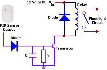
The circuit illustrates a 12V PIR sensor timer circuit diagram. Features include a 12 Volt DC supply, capable of activating a floodlight or other devices for a specified duration. The 12V PIR sensor timer circuit is designed to detect motion...
555 Timer with Audio Alarm Circuit. This circuit serves as a straightforward electronic timer equipped with an audio alarm feature. The 555 timer is a versatile integrated circuit widely used in various timer, delay, pulse generation, and oscillator applications. In...
This circuit features an adjustable output timer capable of re-triggering at specified intervals. The output duration can range from a fraction of a second to over half an hour, with the ability to recur at regular intervals spanning from...
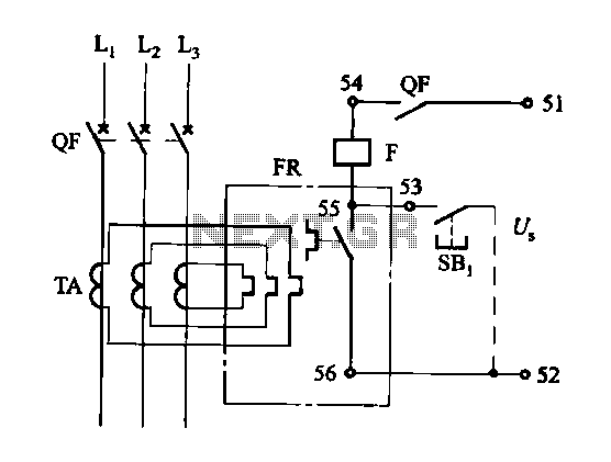
The DK-5A, 5D, and SDb control boxes are equipped with a thermal electromagnetic overcurrent release, as depicted in Figure 6-80. The trip mechanism provides both overload and instantaneous short circuit protection with a long delay feature. In the figure,...
The following circuit illustrates a Cat and Dog Repellent Timer Circuit Diagram. Features include the capability to maintain a deep cycle battery charged by a solar panel. The Cat and Dog Repellent Timer Circuit is designed to provide a humane...
This is a versatile discrete monostable circuit. The circuit consists of a 2N3819 JFET and 2N3704 transistors. This monostable multivibrator circuit has an additional input to enable or inhibit the function at any time without causing an output pulse....