
AVR/Arduino ISP programmer using the Raspberry Pi GPIOs

The design of an ISP programmer using the Raspberry Pi and Atmel AVR microcontrollers can be achieved with a straightforward circuit. The essential components include the Raspberry Pi, the Atmel AVR microcontroller, a buffer (such as a logic buffer or an operational amplifier configured as a buffer), and a FET for level shifting and protection.
The GPIO pins from the Raspberry Pi will be connected to the buffer inputs. The buffer outputs will then connect to the corresponding pins on the AVR microcontroller. This setup ensures that the GPIO pins from the Raspberry Pi are isolated from the microcontroller, preventing potential damage due to voltage mismatches or conflicting logic levels.
The RESET pin of the AVR should be pulled up to the supply voltage using a resistor, and it will be driven low by the Raspberry Pi GPIO to initiate programming. The SCK pin will be connected to a GPIO pin configured as an output, which will provide the clock signal for SPI communication. The MOSI pin will also be connected to a GPIO pin set as an output to send data to the microcontroller, while the MISO pin will be connected to a GPIO pin configured as an input to receive data from the microcontroller.
For programming, the Raspberry Pi will run software like Avrdude, which communicates through the GPIO pins to send commands to the AVR microcontroller. The commands can include reading and writing to flash memory and EEPROM, as well as programming fuses and lock bits. The design allows for a compact solution that leverages the Raspberry Pi's capabilities while providing a robust interface for programming Atmel AVR microcontrollers. Proper attention to the circuit layout and component selection will ensure reliable operation and protection for both the Raspberry Pi and the microcontroller.As a fully-featured Linux computer there are many external programmers that can be used with your Raspberry Pi to program the Atmel AVR range of microprocessors. It`s also possible to use the general purpose input/output lines (GPIOs) found on the Raspberry Pi to implement an ISP programmer with minimal extra hardware.
I say "with minimal extra ha rdware" because although it can be done with no extra hardware I recommend adding a buffer and FET to protect the Raspberry Pi. You might reasonably wonder what is the point if extra hardware should be used since external USB programmers can be bought cheaply from Ebay.
However, if you are going to add an extension PCB to your Raspberry Pi anyway, for instance to communicate with a remote Atmel processor, then including an ISP programmer makes sense and adds very little cost. Most of the Atmel AVR range can be programmed using an ISP interface which resembles the SPI bus. For this description I`ll assume that the SPI pins are reused for this purpose but you should check the datasheet to make sure this is true for your part.
The RESET pin is used as the active-low chip select pin, SCK is the clock signal, MOSI is the input data pin and MISO is the output data pin. If the directions seem odd remember that the microcontroller is acting as a SPI slave in this scenario; with that in mind the names make perfect sense.
The ISP programmer then communicates with the microcontroller, sending commands to read or write flash memory, EEPROM, fuses, and/or locks. Avrdude supports many different programmers which can be used for this task. The simplest interface on the Raspberry Pi is to use four GPIO pins and bit-bang the SPI commands. I don`t recommend this however. After programming has finished the SPI interface on the microcontroller could revert to master mode where SCK and MOSI become outputs.
Connecting two logic outputs together which could be at opposite logic levels is not wise. For a safer interface I used the circuit below. 🔗 External reference
Related Circuits
The TDA7000 is a well-known FM radio receiver integrated circuit (IC), also referred to as a one-chip FM radio receiver. It operates within the VHF FM band, covering frequencies from 70 to 120 MHz. Introduced in the 1980s, the...

This project is a fun and safe activity for individuals interested in magnetically launching projectiles. The operation involves placing a ferromagnetic projectile at one end of a coil and applying a power pulse. The key is to turn off...

A high-quality stereo FM transmitter circuit is presented. This circuit utilizes the BA1404 integrated circuit from ROHM Semiconductors. The BA1404 is a monolithic FM stereo modulator that incorporates a stereo modulator, FM modulator, and RF amplifier circuitry. The FM...
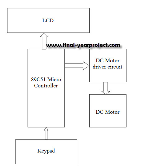
This report details an electronic project focused on the speed control of a DC motor using a microcontroller and PWM (Pulse Width Modulation). The system integrates a microcontroller with an LCD, keypad, and a DC motor driver. The microcontroller...

This circuit responds to RF signals below the standard broadcast band up to over 500 MHz and provides both visual and audible indications when an RF signal is detected. By adjusting the bias of diode D2 with the R2...

This is a short-range light barrier designed for use as an intruder alarm in doorposts and similar applications. The 555 timer in the transmitter oscillates at approximately 4.5 kHz. The short-range light barrier operates by utilizing a transmitter and a...