
Long-Range IR Transmitter
The described IR transmitter circuit is designed to achieve extended operational range and effective signal transmission. The use of three infrared LEDs in series significantly amplifies the emitted power, allowing for reliable communication over longer distances. The choice of a MOSFET as a switching element enhances the efficiency of the circuit, as MOSFETs typically have lower on-resistance compared to bipolar junction transistors, resulting in reduced power loss during operation.
The incorporation of a 100 µF capacitor is a critical design feature, as it provides stability to the power supply during rapid switching events. This is particularly important in battery-operated devices, where voltage fluctuations can lead to erratic behavior. By ensuring a steady voltage supply, the circuit can maintain consistent performance, even under varying load conditions.
The use of a Darlington pair for driving the MOSFET gate is an effective strategy to achieve high input impedance and low output impedance. This configuration minimizes the loading effect on the preceding circuit stage, ensuring that the modulation signal is accurately transmitted to the MOSFET gate without distortion. The modulation of the 38 kHz frequency by the data input allows for efficient encoding of the transmitted information, making the system suitable for various remote control applications.
Overall, this IR transmitter circuit design is an excellent solution for applications requiring long-range infrared communication while maintaining high efficiency and reliability. The integration of commercially available components simplifies the assembly process and enhances the accessibility of the design for hobbyists and professionals alike.Most of the IR remotes work reliably within a range of 5 metres. The circuit complexity increases if you design the IR transmitter for reliable operation over a longer range, say, 10 metres. To double the range from 5 metres to 10 metres, you need to increase the transmitted power four times.
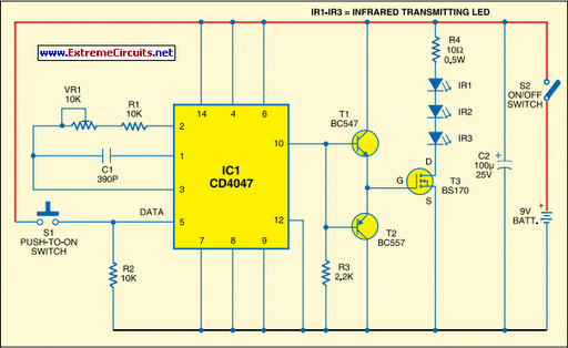
If you wish to real i se a highly directional IR beam ( very narrow beam), you can suitably use an IR laser pointer as the IR signal source. The laser pointer is readily available in the market. However, with a very narrow beam from the laser pointer, you have to take extra care, lest a small jerk to the gadget may change the beam orientation and cause loss of contact. Here is a simple circuit that will give you a pretty long range. It uses three infrared transmitting LEDs (IR1 through IR3) in series to increase the radiated power. Further, to increase the directivity and so also the power density, you may assemble the IR LEDs inside the reflector of a torch.
For increasing the circuit efficiency, a MOSFET (BS170) has been used, which acts as a switch and thus reif a transistor were used. To avoid any dip during its on`/off` operations, a 100 F reservoir capacitor C2 is used across the battery supply.
Its advantage will be more obvious when the IR transmitter is powered by ordinary batteries. Capacitor C2 supplies extra charge during switching on` operations. As the MOSFET exhibits large capacitance across gate-source terminals, a special drive arrangement has been made using npn-pnp Darl ington pair of BC547 and BC557 (as emitter followers), to avoid distortion of the gate drive input. Data (CMOS-compatible) to be transmitted is used for modulating the 38 kHz frequency generated by CD4047 (IC1).
However, in the circuit shown here, tactile switch S1 has been used for modulating and transmitting the IR signal. Assemble the circuit on a general-purpose PCB. Use switch S2 for power on`/off` control. Commercially available IR receiver modules (e. g. , TSOP1738) could be used for efficient reception of the transmitted IR signals. 🔗 External reference
Related Circuits
L2 RFC (resistance 1MOhm with an inductor wrapped around it made from fine isolated wire. Scratch the inductor and connect it to the resistance, creating a parallel L-R circuit.) With C7 and C8, we adjust the resistance of the...
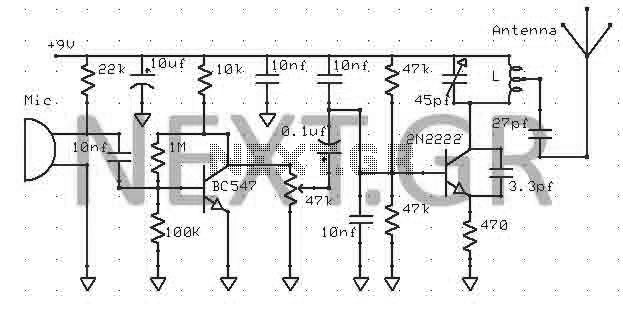
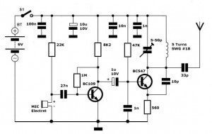
This transmitter can be powered by a 9V battery (not exceeding 12V). Users can connect a music source at the microphone input or utilize a simple condenser microphone. The signal range can reach up to 400 meters in open...
The original TX was designed to be only PULSE Modulated for a proportional R/C system, but I later used the same circuit to make an HF bands Amplitude Modulation (AM) transmitter using PA-Base Modulation. It eliminated the need for...
This AM radio circuit is a low-power transmitter operating in the broadcast band. Its simplicity is achieved through the use of a single-transistor amplifier stage. The AM radio transmitter circuit operates within the standard AM broadcast band, typically ranging from...

3V FM Transmitter Circuit. This project provides the schematic and parts list needed to construct a 3V FM transmitter. This FM transmitter is one of the simplest and most basic transmitters to build, offering a useful transmitting range. The 3V...
Simple FM Transmitter Circuit This simple FM transmitter circuit was built using a transistor with a transmission distance of about 300m around your home. The simple FM transmitter circuit utilizes a transistor to modulate audio signals onto a radio frequency...