
Programmable Timer of timer circuit
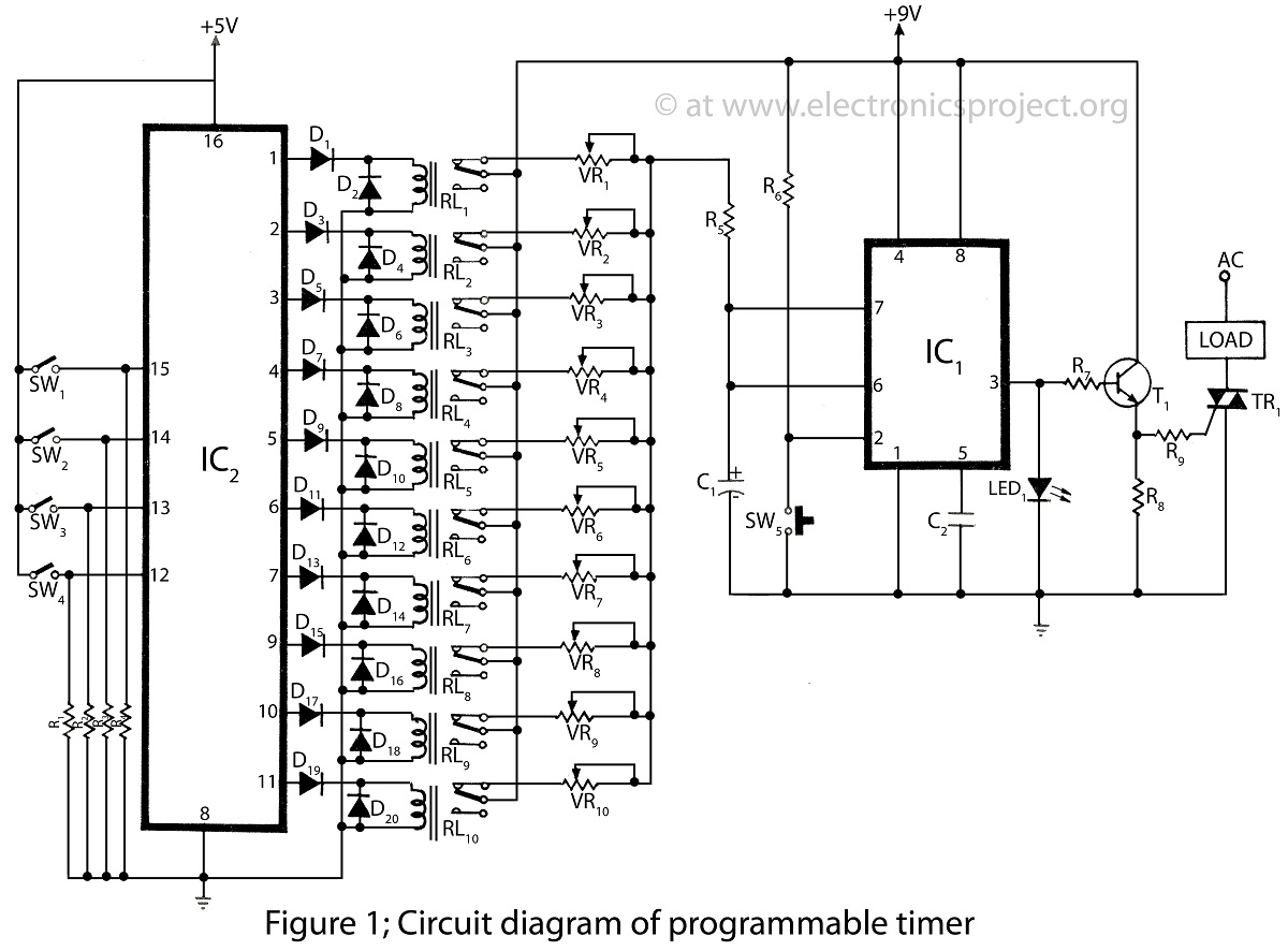
The programmable timer circuit typically consists of two primary integrated circuits: a timer IC, such as the NE555 or its variants, and a microcontroller or a second timer IC for added functionality. The NE555 timer can be configured in either monostable or astable mode, allowing for versatile timing applications.
In monostable mode, the timer generates a single pulse of a specified duration when triggered. This is useful for applications requiring a delay or a timed event. The duration of the pulse can be adjusted by changing the resistor and capacitor values connected to the timer IC.
In astable mode, the NE555 functions as an oscillator, producing a continuous square wave output. This mode is ideal for generating clock pulses, flashing LEDs, or driving other timing circuits. The frequency and duty cycle of the output waveform can be modified by altering the resistor and capacitor values in the circuit.
The second IC can serve various purposes, such as enhancing the timer's capabilities or providing additional features like programmable intervals. A microcontroller can be programmed to control the timing functions and provide user interfaces, such as buttons or displays, for setting the timer duration and mode.
The circuit design should include power supply considerations, typically using a regulated voltage source suitable for the chosen ICs. Proper decoupling capacitors should be placed near the power pins of the ICs to ensure stable operation.
Overall, the programmable timer circuit is a versatile and essential component in various electronic projects, ranging from simple timers to complex automation systems. Its simplicity and adaptability make it an excellent choice for both beginners and experienced engineers in the field of electronics.Programmable Timer in this website is very simple made from only 2 iC of wide range circuit and description of programmable timer various timer project. 🔗 External reference
Related Circuits

This circuit is for an audio equalizer that is commonly found in commercial products such as high-fidelity systems, car audio, and stage equipment; however, published circuits for these devices are quite rare. This design features equalizer bands. The circuit...
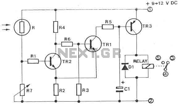
The circuit is a light switch that activates when the light intensity drops on a photoresistor. It features a straightforward construction and can be utilized in numerous applications. The photoresistor and the trimmer function as a voltage divider and...
An FM transmitter circuit that utilizes a low power configuration, employing an operational amplifier as an audio preamplifier and a single transistor to function as the RF amplifier. This FM transmitter circuit is designed for low power applications, making...
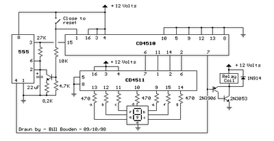
When the switch is opened, the timer generates an approximate 1-second clock signal, decrementing the counter until it reaches a count of zero. Upon reaching zero, the carry-out signal at pin 7 of the counter goes low, energizing a...
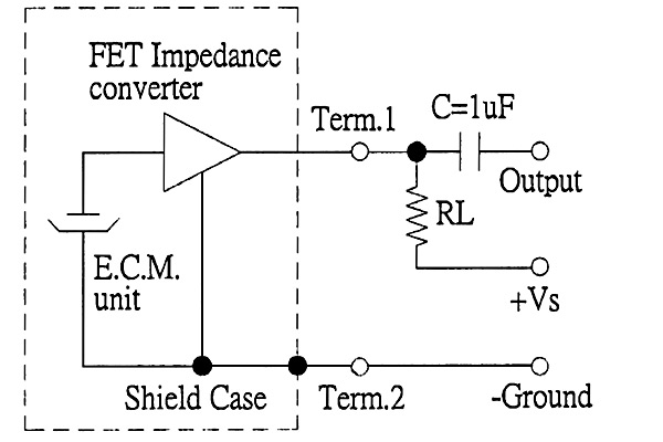
The back of the electret microphone resembles the drawings of the CUI Inc part number CMA-4544PF-W, which will be included in the parts kit. While debugging the data logger software on Windows, an oscilloscope practice lab was conducted using...
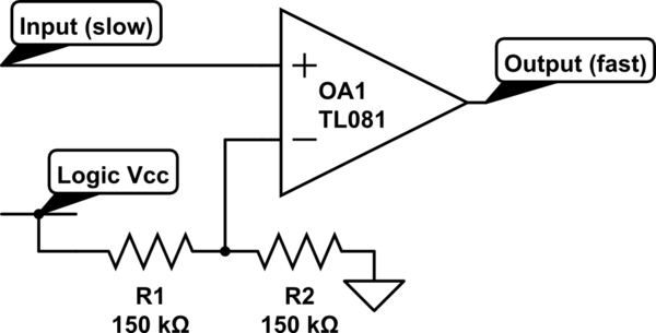
Invert a signal to drive FETs with rapid rise and fall times. It was suggested to use an inverter (not a chip) instead of logic chips, which are designed to be either fully ON or OFF. The individual has...
Warning: include(partials/cookie-banner.php): Failed to open stream: Permission denied in /var/www/html/nextgr/view-circuit.php on line 713
Warning: include(): Failed opening 'partials/cookie-banner.php' for inclusion (include_path='.:/usr/share/php') in /var/www/html/nextgr/view-circuit.php on line 713