
Loudness control
An electronic schematic utilizing the NE5532 operational amplifier can be designed to create a versatile audio processing circuit. The NE5532 is a dual low-noise operational amplifier known for its high performance, making it suitable for audio applications. The circuit can be divided into three main frequency response blocks: flat, bass, and treble.
The flat block serves as a reference point, allowing the audio signal to pass through without significant alteration. This block should be configured to maintain a unity gain, ensuring that the signal integrity is preserved.
The bass block is designed to enhance low-frequency signals. To achieve this, a low-pass filter configuration can be employed, which will allow frequencies below a certain cutoff to pass while attenuating higher frequencies. The cutoff frequency can be calculated using the formula \( f_c = \frac{1}{2\pi RC} \), where \( R \) is the resistance and \( C \) is the capacitance in the filter circuit.
The treble block focuses on amplifying high-frequency signals. This can be implemented using a high-pass filter, which permits frequencies above a specified cutoff to pass through. Similar to the bass block, the cutoff frequency can be calculated using the same formula, adjusting the values of \( R \) and \( C \) to suit the desired frequency response.
A buffer stage should be included at the input of the circuit to prevent loading effects that could degrade the signal. This buffer can be implemented using one of the NE5532 op-amps configured as a voltage follower, providing high input impedance and low output impedance.
To facilitate user interaction, trimpots or fixed resistors can be integrated into the circuit to allow for manual adjustment of gain or frequency response. Additionally, buttons can be implemented to switch between the different processing modes (flat, bass, treble), enabling the user to select the desired sound profile.
Overall, this schematic provides a flexible audio processing solution, allowing for tailored frequency response adjustments while maintaining high audio fidelity. Proper attention to component selection and configuration will ensure optimal performance in the intended application.First you will have to use a opamp like ne5532, than calculate the frequency you want on each block(on block for flat, one for bass and one for high), don`t forget to put a buffer on the first stage, you can use trimpots or fixed resistor and some bottons to activate what you want on the circuit. Specific for your aplication you will have to do it by yourself, but i can help. First you will have to use a opamp like ne5532, than calculate the frequency you want on each block(on block for flat, one for bass and one for high), don`t forget to put a buffer on the first stage, you can use trimpots or fixed resistor and some bottons to activate what you want on the circuit. 🔗 External reference
Related Circuits
The heart of the PWM Fan Controller is a PIC 12F675 microcontroller. This microcontroller is reading the analog output of a LM35 temperature sensor using a ADC (analog to digital converter). The resulting digital value is converted to a...
The circuit above illustrates using the IR receiver module along with a PIC12F629 microcontroller to decode 5 individual IR remote control keys so the circuit will only toggle one of the 4 outputs when a particular key is pressed....
This circuit disrupts the infrared receiver in a television by generating a continuous signal that interferes with the remote control signals, preventing the TV from recognizing channel changes or other commands. This allows for uninterrupted viewing of a chosen...
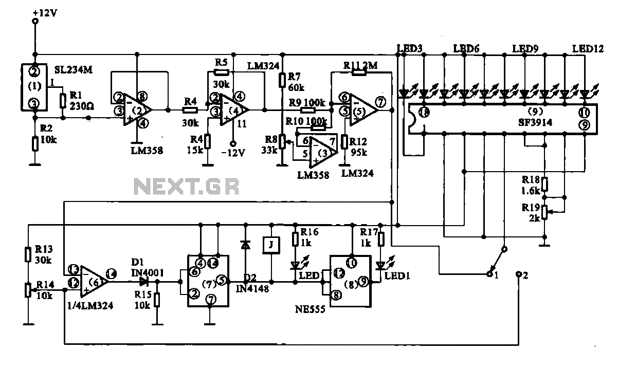
Vegetable greenhouse temperature detection control circuit. The greenhouse temperature detection control circuit is primarily composed of a temperature sensor SL234M, operational amplifiers LM324 and LM358, a dual time base circuit NE555, a relay, and a display driver circuit. The...
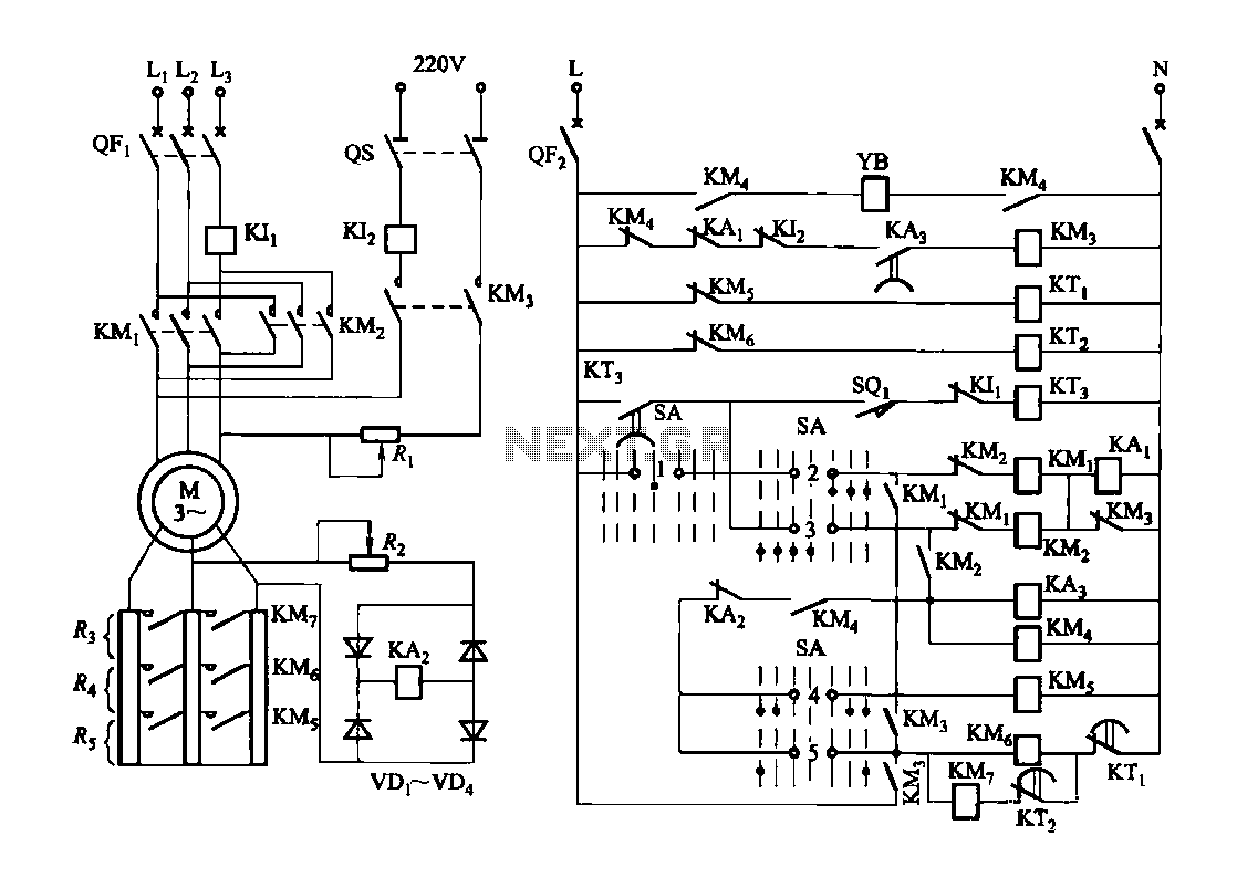
Figure 3173 illustrates a control circuit for a wound rotor induction motor that enables mechanical braking, dynamic braking, and reverse braking functions. The circuit includes various components such as relays, contactors, and time relays to manage the motor's speed...
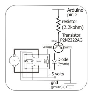
To control the motor, an H-bridge will be utilized in conjunction with a double-pole double-throw (DPDT) relay, as illustrated in the schematic below. For further details, additional resources are available. The proposed circuit employs an H-bridge configuration to facilitate bidirectional...