
Motor controller H-bridge using relays

The proposed circuit employs an H-bridge configuration to facilitate bidirectional control of a DC motor. The H-bridge consists of four switches (transistors or MOSFETs) arranged in a bridge configuration, allowing for the reversal of current flow through the motor, enabling it to rotate in both clockwise and counterclockwise directions.
The integration of a DPDT relay enhances the circuit's functionality by providing an alternative method for reversing the motor direction. The relay can be operated by a microcontroller or a manual switch, enabling the user to select the desired motor operation mode. When the relay is activated, it connects the appropriate terminals of the H-bridge to the power supply, allowing for seamless control over the motor's direction.
In terms of component selection, the transistors or MOSFETs used in the H-bridge should be rated for the motor's voltage and current requirements to ensure reliable operation. Additionally, flyback diodes should be included across the switches to protect against voltage spikes generated when the motor is turned off.
The control logic for the H-bridge can be implemented using a microcontroller, which can provide PWM (Pulse Width Modulation) signals to control the speed of the motor. By varying the duty cycle of the PWM signal, the effective voltage applied to the motor can be adjusted, allowing for precise speed control.
Overall, this circuit design provides a robust solution for motor control applications, combining the versatility of an H-bridge with the reliability of a DPDT relay.To control the motor, i will be using an H-bridge with a DPDT relay like you can see on this schematic below. If you want more details, look on this.. 🔗 External reference
Related Circuits
The circuit is constructed using two 555 timer integrated circuits, designated as U1 and U2. U1 is configured as a variable duty cycle oscillator with a fixed time period of approximately 0.1 seconds. The duty cycle can be adjusted...
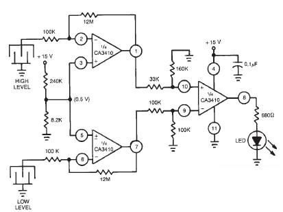
This liquid level sensor electronic circuit diagram utilizes a common CA3410 operational amplifier integrated circuit (IC). The sensor employs two plate sensors (or probes), one designated for detecting high liquid levels and the other for low liquid levels. If...
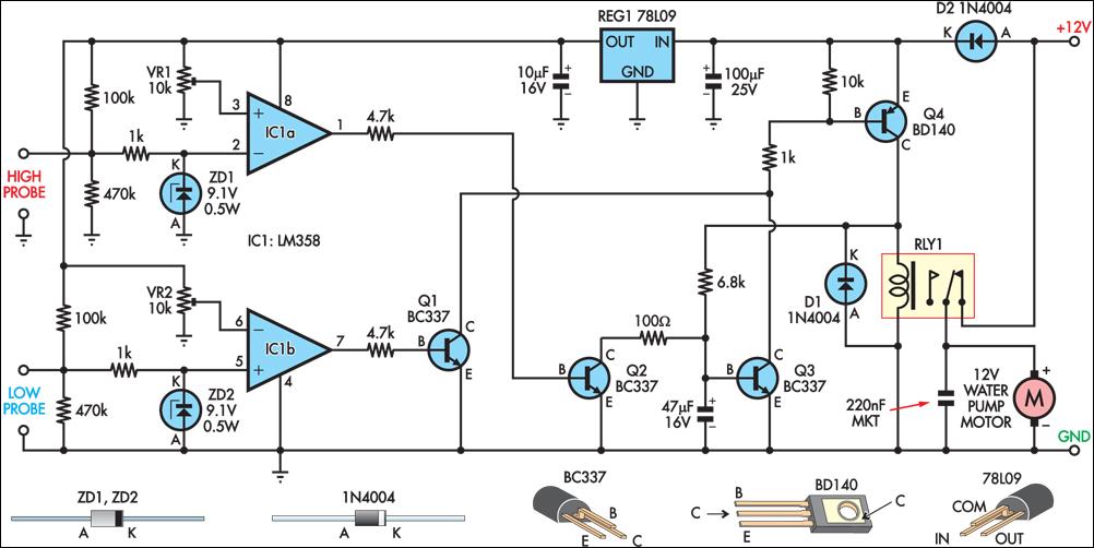
This circuit operates an automotive windscreen washer pump to fill a 20-litre drum from a 205-litre water reservoir. The drum is suspended above a drip line, which irrigates a vegetable garden. Two stainless steel probes mounted in the drum...
In this figure, S1 initiates the timing process, and once the timer is activated, toggling this switch will not impact the timing operation. S2 serves as the OFF switch located in the center; toggling this switch allows the timer...
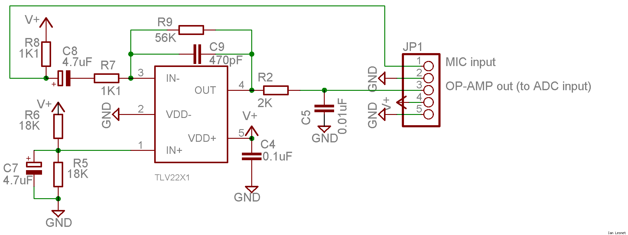
This project utilizes a small, common electret microphone to convert audio into an electrical signal. These inexpensive microphones are typically found in most PC headsets. The output from the microphone must be amplified and zeroed before it can be...
This decibel meter circuit responds to sound pressure levels ranging from approximately 60 to 70 dB (decibels). The sound is captured by an 8-ohm speaker and amplified using a transistor stage along with an LM324 operational amplifier section. A...