
Bicycle Rear-Light Afterglow Circuit

The described circuit utilizes a dynamo to power bicycle lights, integrating a series of components to ensure effective illumination while conserving battery power. The dynamo generates alternating current (AC), which is converted to direct current (DC) through bridge rectifier B1. This component comprises four diodes arranged in a bridge configuration, allowing current to flow in a single direction, thereby charging capacitor C2.
The low-dropout regulator IC1 is essential for maintaining a consistent output voltage of +5 V, regardless of variations in the input voltage generated by the dynamo. This regulated voltage is crucial for the stable operation of the LEDs and the timer circuit. The timer IC2, configured as an astable multivibrator, generates a square wave output that controls the on/off cycling of the LEDs. The duty cycle of 10% means that the LEDs are illuminated for a brief period compared to the time they are off, significantly reducing power consumption.
Capacitor C2 serves as an energy reservoir, storing charge when the bicycle is in motion. When the bicycle comes to a stop, the stored energy in C2 is used to power IC2, which delays the activation of the LEDs for 0.25 seconds after the bicycle is stationary. This feature enhances visibility and safety by ensuring that the rear light remains illuminated even when the cyclist is at a standstill, such as at traffic signals.
In summary, the circuit design effectively combines a dynamo-powered system with intelligent timing and regulation to ensure that bicycle lights operate safely and efficiently, adhering to stringent regulations while promoting cyclist visibility. The careful selection of components and their configuration plays a vital role in achieving the desired functionality and performance of the lighting system.This article is of interest only to readers whose bicycle lights are powered by a dynamo. The laws on bicycle lights in the United Kingdom are stricter than in most other countries and a dynamo is, therefore, a rarity in the UK. For safety`s sake, it is obligatory for cyclists in the UK to have the rear light of their bicycles on even when they ar
e at standstill. Such a rule is, of course, also advisable in other countries, even when it is not mandatory. The super-luminous LEDs are not powered directly by the regulator, IC1, but via a timer, IC2. The timer is driven by a pulsating voltage with a duty factor of 10%. This ensures very low current drain and also that the reservoir capacitor, C2, can energize the LEDs for a long time. Capacitor C2 is charged when the bicycle, and thus the dynamo if this makes contact with the relevant wheel, is ridden.
This happens via bridge rectifier B1, and low-drop regulator IC1. The output of the regulator is a steady +5 V. When the bicycle is in use, but at standstill, for instance, at traffic lights, the potential across C2 powers astable multivibrator (AMV) IC2. With component values as specified, the switch-on time is about 0. 02 s, but the LEDs are not energized until 0. 25 s have elapsed. 🔗 External reference
Related Circuits
This is a simple and cost-effective inverter designed to power a small soldering iron (25W, 35W, etc.) in situations where a mains supply is unavailable. The circuit utilizes eight transistors. The inverter circuit operates by converting DC voltage from a...

This electronic RF detector project is constructed using common transistors and a few standard electronic components. The RF detector is capable of responding to RF signals below the standard broadcast band and extending to over 500 MHz, providing both...

A very simple FM IF MW radio receiver circuit can be designed using the LA1260 IC manufactured by Sanyo Semiconductor. This FM IF MW radio receiver circuit schematic shows that the LA1260 IC can be utilized in AM and...
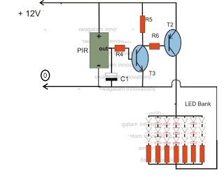
The circuit is an LED driver that responds to ambient light as well as the presence of an intruder, varying its illumination accordingly. Additionally, it includes an ambient light sensor to turn the LEDs on and off, and a...
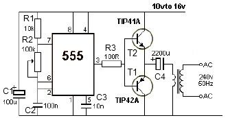
This 12V power inverter circuit can be utilized to power small devices that require 240 volts. It is particularly advantageous for operating 240-volt appliances using a 12-volt car battery. Unlike typical feedback oscillator inverters, this design employs a 555...
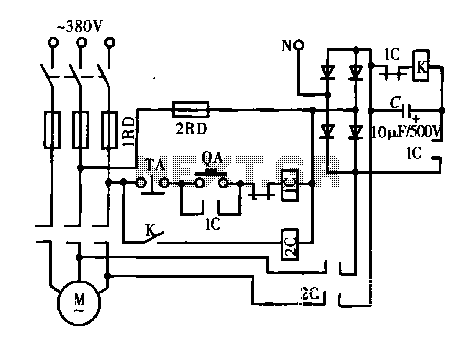
A DC motor is depicted in a dynamic braking circuit. When the stop button (SB2) is pressed, the contactor (KM1) is deactivated, causing its movable contact to disconnect, which interrupts the electrical voltage. Additionally, relay (KV) is activated, closing...
Warning: include(partials/cookie-banner.php): Failed to open stream: Permission denied in /var/www/html/nextgr/view-circuit.php on line 713
Warning: include(): Failed opening 'partials/cookie-banner.php' for inclusion (include_path='.:/usr/share/php') in /var/www/html/nextgr/view-circuit.php on line 713