
Telephone Line Indicator Circuit
The circuit design for the voltmeter to monitor telephone line status includes essential components that ensure accurate readings while maintaining user safety. The moving coil meter serves as the primary indicator, displaying the voltage levels corresponding to different states of the telephone line. The bridge rectifier is crucial for converting the AC voltage from the telephone line into a DC voltage suitable for the moving coil meter.
The series resistor plays a vital role in determining the current flowing through the meter, which directly impacts the deflection observed. The selection of this resistor is based on the meter's full-scale sensitivity. For instance, using a 250 µA VU meter, a resistor value of 390 kΩ allows for optimal performance, ensuring that the meter indicates approximately two-thirds deflection when the line is idle. Conversely, for a more sensitive 100 µA meter, a higher resistance of around 680 kΩ is required to achieve similar deflection characteristics.
The operational states of the telephone line are defined by specific voltage ranges that correspond to the deflection of the meter. A small deflection indicates that the line is active, with a voltage typically ranging from 5 to 12 V, reflecting current usage. A two-thirds deflection signifies that the line is idle, with a nominal voltage of around 48 V, while full-scale deflection indicates the presence of a ringing signal, which can range from 60 to 90 V AC.
Safety considerations are paramount, especially given the high voltages involved. The design should incorporate features to ensure that users can safely interact with the circuit without risk of electric shock. This can include utilizing insulated components, ensuring proper casing, and implementing design techniques that minimize exposure to high voltage areas. Overall, the circuit presents a practical solution for monitoring telephone line status while prioritizing user safety and ease of use.With the aid of an (old) moving coil instrument it is very little effort to make a simple voltmeter that, at a glance, indicates the status of a telephone line. Because the input impedance of this circuit is very high, there is no problem in having it permanently connected to the line, since it only draws a tiny amount of current.
The schematic sh ows that the circuit consists of no more than a series resistor, a bridge rectifier and a moving coil meter. The value of the resistor depends on the sensitivity of the moving coil meter. In his prototypes, the author used old VU meters that require 250 µA for full-scale deflection. A resistor value of 390 k appeared to be optimal for these meters. For a 100- µA-instrument, this resistor value will have to be increased to about 680 k. The starting point, when selecting a resistor value is that when the telephone is not in use, the meter should de ¬‚ect about 2/3rd of full scale.
The amount of meter deflection indicates the three different states of the telephone line: 1. The deflection is very small: the line is in use (voltage 5 to 12 V). 2. The deflection is 2/3rd of full scale: the line is not in use (voltage typically 48 V). 3. Full-scale deflection: ring signal (60 to 90 V AC). Because the idle voltage and certainly the ring voltage are high enough to be dangerous, it is recommended that the circuit is constructed in such a way that it presents no hazard when touched. 🔗 External reference
Related Circuits

This power inverter circuit provides a stable square wave output voltage. The frequency of operation is set by a potentiometer and is typically adjusted to 60 Hz. Various off-the-shelf transformers can be utilized, or custom-wound transformers can be created...

The circuit utilizes a Bute CD12V Lee power MOSFET transistor (BU1RF744) that operates in a switching mode, turning on and off repeatedly. The output voltage is influenced by the characteristics of the MOSFET, which is designed for efficient performance....
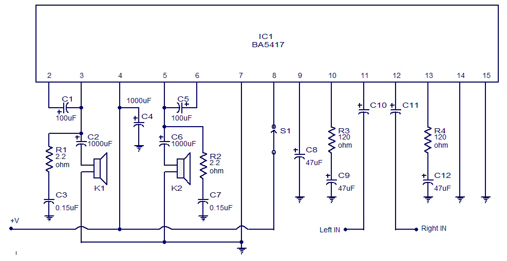
The BA5417 is a stereo amplifier integrated circuit (IC) that features several advantageous characteristics, including thermal shutdown, a standby function, soft clipping, and a wide operating voltage range. It can deliver 5 watts per channel into 4-ohm loudspeakers when...

A common intermediate frequency amplifier circuit is presented, along with its components and parameters. The reference values for the components are as follows: 1) Transistors: VT1 to 3DG19, Vcc = 6V. 2) Resistance values: R1 = 50 kΩ, R2...

When the ignition switch is activated, relay K1 receives continuous power, allowing the headlights to be turned on. When the ignition is turned off, timer IC1 is activated, maintaining its power for a duration determined by resistor R1 and...
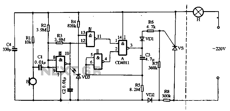
The main circuit utilizes a two-input NAND gate composed of four digital integrated circuits. This includes a NAND gate microphone amplifier circuit, a light control mechanism using an "AND gate," and a monostable delay control circuit formed by NAND...