
Low-Cost Audio Delay Line Uses 1-Bit ADC

The analog delay line circuit presented by Jim Walker utilizes the LM311 comparator and the 74HC74 D flip-flop to achieve a cost-effective solution for signal delay applications. The LM311 is a versatile voltage comparator that can be employed to detect the threshold levels of an input signal and produce a corresponding output. The 74HC74 is a dual D-type flip-flop, which can be used for storing binary information and is capable of providing edge-triggered operation.
In this circuit, the LM311 is configured to compare the input signal against a reference voltage. When the input signal exceeds the reference level, the output of the LM311 changes state, which can be used to trigger the 74HC74 flip-flop. The flip-flop then captures the input signal state at the moment of the triggering event, effectively introducing a delay based on the clock frequency applied to the flip-flop.
The design can be adjusted to modify the delay time by changing the clock frequency or by introducing additional components, such as resistors and capacitors, that influence the timing characteristics. This flexibility allows for a wide range of applications, including audio signal processing, data communication, and pulse width modulation.
Overall, the combination of the LM311 comparator and the 74HC74 D flip-flop in this analog delay line circuit provides a simple yet effective means of achieving controlled signal delays at a minimal cost, making it suitable for various electronic projects and applications.Author Jim Walker describes a very low cost analog delay line circuit using parts such as the LM311 comparator and 74HC74 D flip-flop. 🔗 External reference
Related Circuits
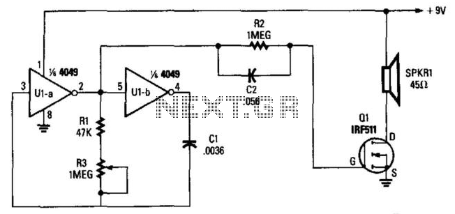
Two gates, U1A and U1B, of a 4049 hex inverter, are connected in a VFO circuit. Components R1, R3, and C1 set the frequency range of the VFO. With the given values, the circuit's output can range from a...
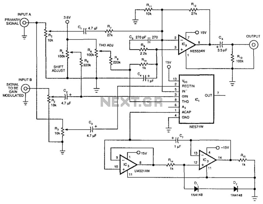
The dynamic mixer combines two audio inputs by adding the primary signal, Input A, to a gain-controlled signal, Input B. The unique feature of this circuit is that the average voltage level of Input A controls the gain of...

The circuit below demonstrates the generation of a single positive pulse that is delayed in relation to the trigger input time. It is similar to a previously described circuit but utilizes two stages, allowing for control over both the...
Many a times one needs an extra telephone ringer in an adjoining room to know if there is an incoming call. For example, if the telephone is installed in the drawing room you may need an extra ringer in...
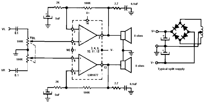
Non-inverting audio amplifier schematic. This non-inverting audio amplifier circuit can be utilized in multi-channel audio systems, stereo phonographs, tape recorders and players, AM-FM radio receivers, servo amplifiers, intercom systems, and automotive products. The audio amplifier described here employs two...
The AH1751 is a single digital output Hall-effect sensor designed for high-temperature operation. This device features an on-chip Hall voltage generator for magnetic sensing, an amplifier to enhance the Hall voltage, and a comparator that offers switching hysteresis to...