
Low-Cost Dual Digital Dice
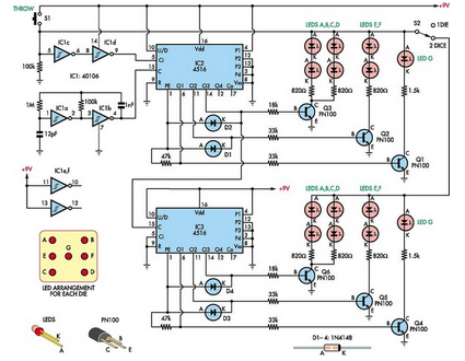
The dual digital dice circuit utilizes three low-cost integrated circuits to create a simple yet effective random number generator. The primary components include two oscillators (IC1a and IC1b), which generate clock pulses at a defined frequency. These oscillators are typically configured using a 555 timer IC or similar, producing a square wave output that drives the subsequent logic in the circuit.
Transistors are employed to amplify signals and control the operation of the LEDs, which visually represent the dice rolls. The LEDs are arranged in a manner that allows them to light up in patterns corresponding to the numbers displayed on traditional dice. The circuit can be designed to show numbers from one to six for each die, with the output being triggered by a push-button switch or a similar input mechanism.
The circuit's operation begins when the user activates the switch, causing the oscillators to start generating clock pulses. These pulses are fed into a binary counter or a similar digital logic component, which counts the pulses and determines the output state. As the counter increments, it activates the appropriate LEDs to reflect the current count, simulating the roll of two dice.
To enhance the user experience, additional features can be integrated, such as sound effects using a small speaker or buzzer that activates with each roll, or a reset function that allows the user to clear the displayed numbers. The design can be compact, making it suitable for portable applications or as a fun addition to board games. Overall, this dual digital dice circuit combines simplicity and functionality, making it an excellent project for electronics enthusiasts.This simple dual digital dice is based on three low-cost ICs, a few transistors and a handful of LEDs. IC1a & IC1b operate as an oscillator with a frequen.. 🔗 External reference
Related Circuits
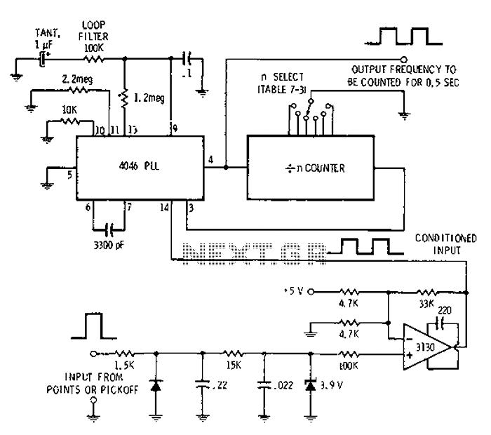
Automotive engine pulse points or other sensors are filtered using the transmission device 3130 CMOS operational amplifier, which functions as a comparator to fulfill the input conditions. The pulse subsequently flows into a 4046 phase-locked loop (PLL) N-counter, which...
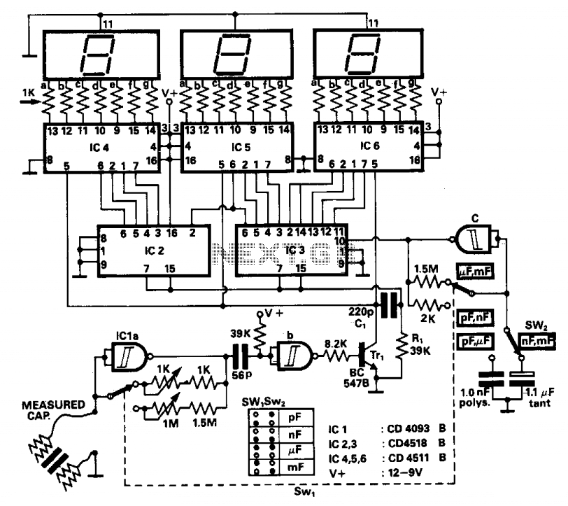
The operation principle involves counting the number of pulses generated by a constant frequency oscillator over a fixed time interval, which is produced by another lower frequency oscillator. This lower frequency oscillator utilizes the capacitor being measured as the...
U1 is the 3817 integrated circuit, capable of directly driving the display. It can show time in either 12-hour or 24-hour format, schedule alarm sounds, and automatically turn on the radio at specified times. The display utilizes the FND500...
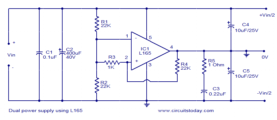
This dual power supply utilizes the L165 power operational amplifier from SGS-Thomson Microelectronics. The L165 IC can deliver up to 3.5A of current, with internal current limiting. It is available in a Pentawatt package, making it well-suited for power...

This low-cost function generator, based on the Maxim MAX038 high-frequency waveform generator, produces sine, triangle, and square waves from under 1 Hz to over 20 MHz. The function generator utilizing the Maxim MAX038 is designed to provide a versatile range...
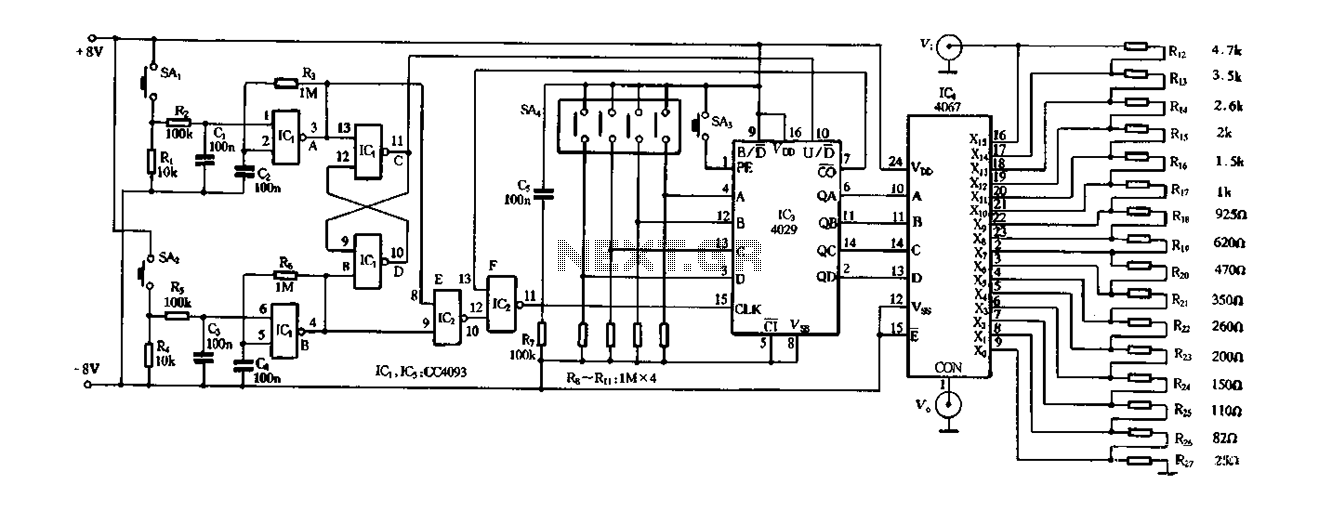
Figure 4-14 illustrates a digital integrated circuit featuring 16 preset potentiometers for Siniperca electronic circuits. The circuit comprises three main components: an input controller, a presettable counter, an analog electronic switch, and a resistor network. It includes a push-button...