
low cost high speed photography
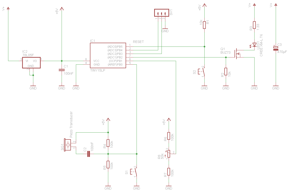
The schematic design incorporates a linear voltage regulator to supply a stable voltage to the controller, enhancing the reliability of the system. The variable voltage generator on PB1 allows for fine-tuning of the reference voltage, which is critical for the accurate operation of the sensor circuit. The voltage divider, configured to output 2.5 volts, ensures that the signal input aligns with the expected operational parameters of the transducer, allowing it to detect changes in the environment effectively.
In terms of the sensor's performance, the sensitivity is a double-edged sword; while it enables the detection of subtle changes, it also increases the likelihood of false triggers. The integration of an operational amplifier could significantly improve the signal-to-noise ratio, thereby reducing erroneous activations caused by ambient light changes, such as the switching of room lights.
The implementation of a dead time parameter set to four seconds serves as a practical approach to mitigate the effects of false triggering by ensuring that the sensor does not respond to rapid successive stimuli. This feature is particularly beneficial in applications such as photography, where precise timing is essential to capture the desired moment without interference.
Overall, this circuit design not only facilitates the exploration of dynamic phenomena like water droplets but also encourages users to engage in further experimentation and learning within the realm of sensor technology and photography. The combination of a well-calibrated reference voltage, a robust sensor circuit, and thoughtful timing parameters creates a versatile platform for capturing unique visual representations of physical processes.And here is the final part of the entry, starting with the schematic that I finally used. The core is the same as before. But now there is a linear voltage regulator for the controller. Also shown here is the serial interface and most importantly, the sensor circuit. The sensor circuit consists of two parts. First, the reference voltage on PB1 is generated with a variable voltage generator. The voltage can be varied between 2 and 3 volts. The second part is the signal input, also a voltage divider at 2. 5 volts and the transducer. I adjusted the reference voltage so that the LED just stops flashing without any input activity. Everything works. The main improvement would probably be on the sensor. It has to be very sensitive, and this leads to false triggers. E. g. switching the room light on or off trigger it. Perhaps an amplifier would help. As a work-around I set the dead time parameter to four seconds, so it would only trigger once per photo. I was able to take a few really interesting pictures. It is quite amazing how water behaves and the stroboscope makes it possible to explore that. I put a few pictures on flickr and there will be more. It is quite useful to look at some howtos on water drop photography. And of course you can experiment quite a lot. 🔗 External reference
Related Circuits
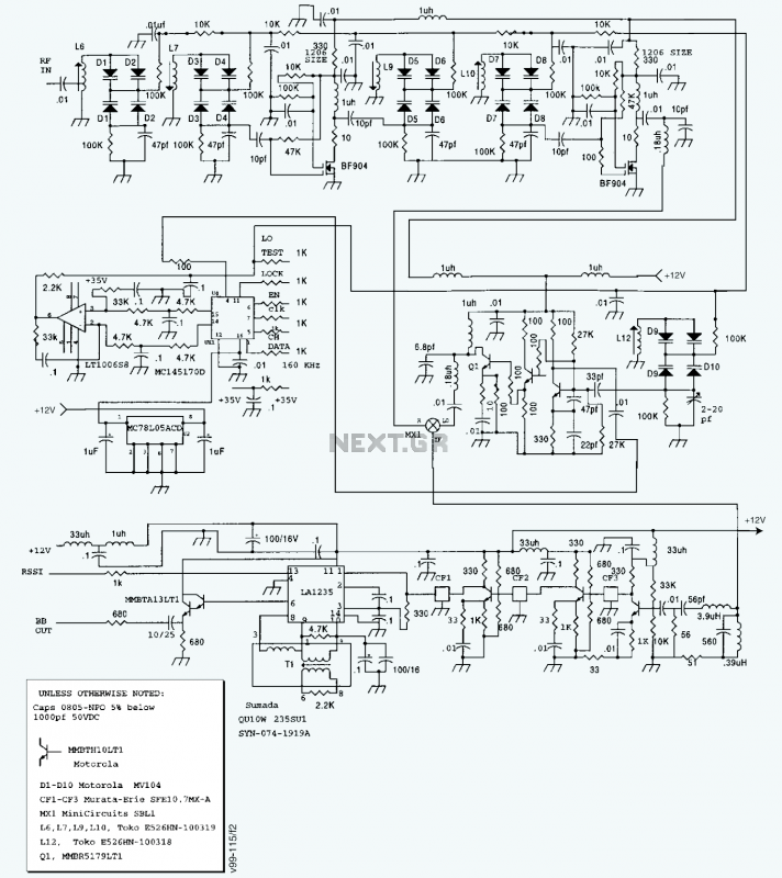
A block diagram and a schematic of the receiver are shown in Figures 2 and 3, respectively. In Figure 3, L6 and L7 are spaced 0.6 inch for a loss of about 0.5 dB. Q4 is the first RF...
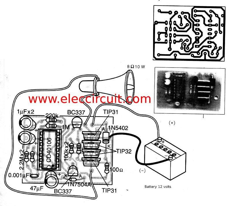
This is a simple siren sound generator with high power output and significant noise. The circuit utilizes digital ICs, specifically the CD4046, in an inverter configuration, along with four transistors to amplify the current output to a horn speaker...
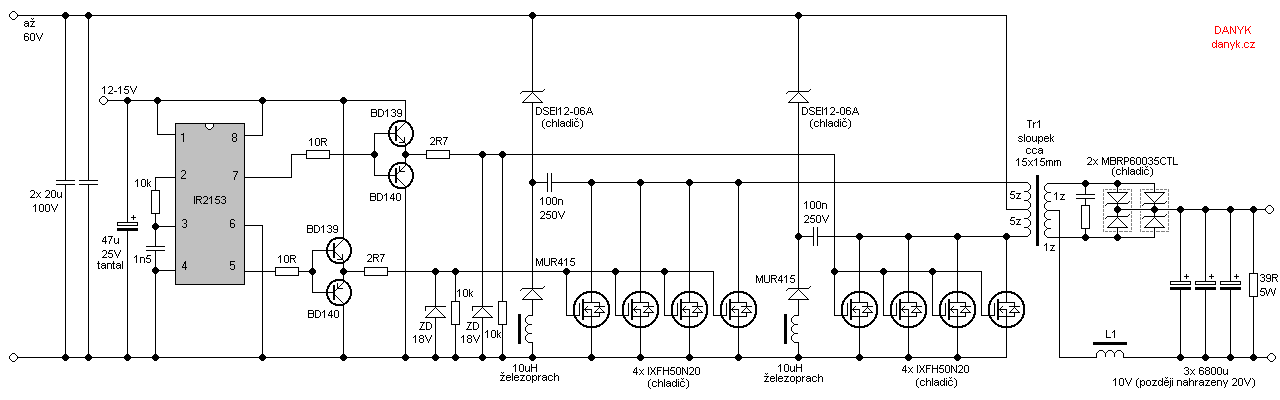
Occasionally, a low voltage power supply capable of delivering very high currents (hundreds of amperes) is required for applications such as spot welding, heating or melting metals, starting vehicle engines, or conducting various physical experiments. A decision has been...
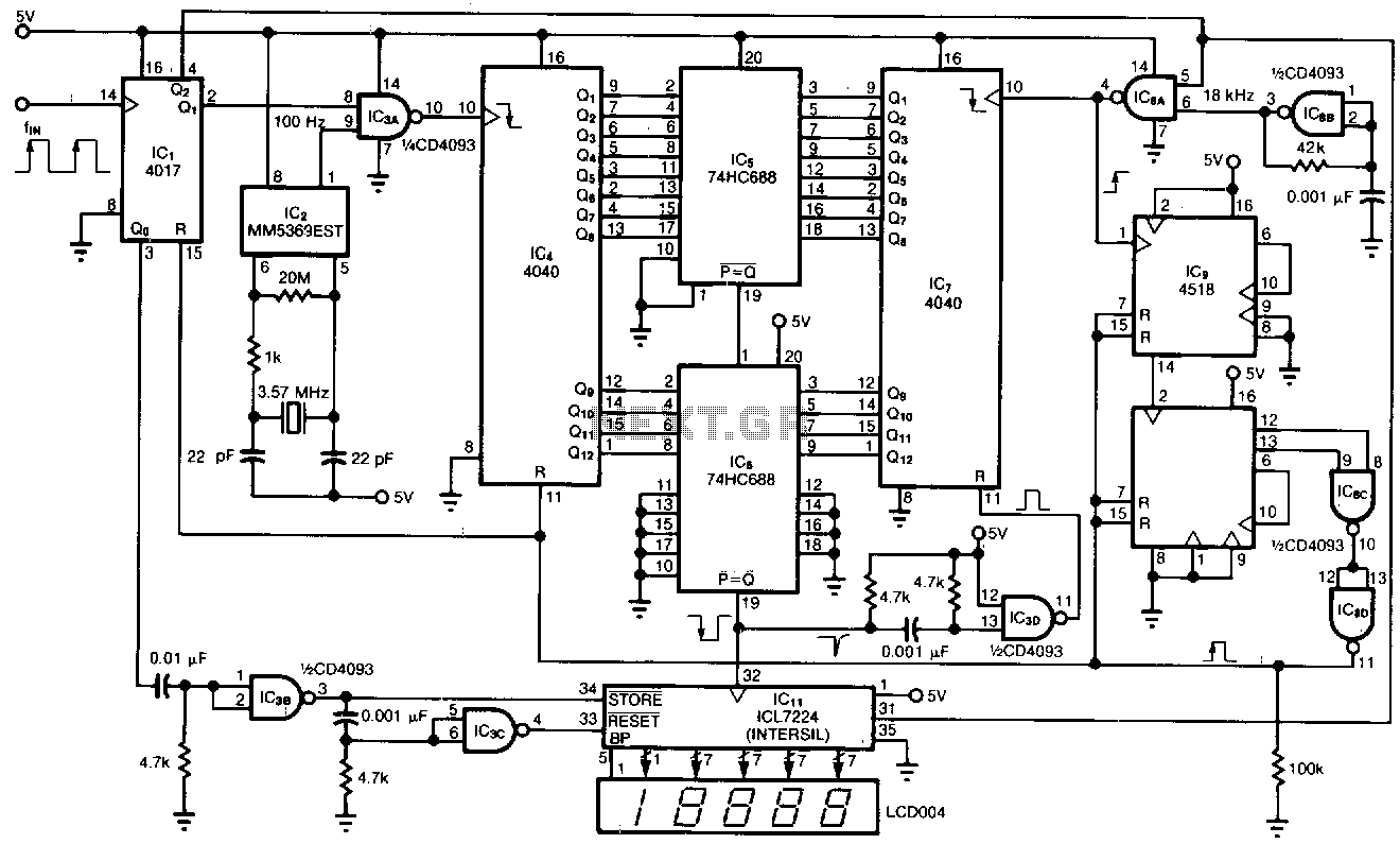
This tachometer allows for the measurement of heartbeats, respiratory rates, and other low-frequency events that occur at intervals ranging from 0.33 to 40.96 seconds. The circuit detects the frequency, calculates the corresponding pulses per minute, and updates the LCD...
Neon glow lamps can be utilized solely for their voltage/current characteristics rather than for illumination. These lamps are electrically similar to diacs; no current flows through them when the voltage is below a trigger value (approximately 70V for neon...
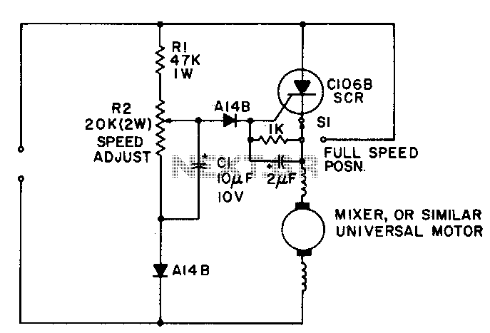
A simple half-wave motor speed control is effective for use with small universal (AC/DC) motors, featuring a maximum current capability of 2 amps RMS. The control provides speed-dependent feedback, ensuring excellent torque characteristics for the motor, even at low...