
Odd application of neon glow lamps

Neon glow lamps serve dual purposes in electronic circuits: they can function as indicators or as components in triggering mechanisms, capitalizing on their unique voltage/current characteristics. In dimmer circuits, they effectively replace diacs to control the operation of triacs, contributing to the regulation of power delivered to lighting systems. The implementation of an RC network allows for precise timing adjustments, ensuring that the triac is triggered at the desired moment, thus facilitating smooth dimming capabilities.
In stroboscope applications, the neon glow lamp's ability to act as a trigger is essential for the operation of xenon tubes, which produce brief bursts of light. This functionality is vital in photography and entertainment, where synchronized flashes are required. The careful design of the charging circuit, utilizing high-voltage capacitors, ensures that sufficient energy is stored to produce the desired flash intensity.
The innovative use of neon glow lamps as electromagnetic field detectors highlights their versatility beyond conventional applications. By integrating simple components such as UJT transistors and transformers, these lamps can be transformed into sensitive monitoring devices. The calibration process involving a trimmer allows users to fine-tune the sensitivity of the detector, making it a practical tool for identifying electromagnetic interference from various sources, including communication devices.
Safety precautions are paramount when working with circuits involving high-voltage components such as electrolytic capacitors. Proper discharge methods must be implemented to prevent accidental electric shock, ensuring safe handling during maintenance and testing. Overall, the multifaceted applications of neon glow lamps illustrate their importance in both practical and experimental electronic designs.Neon glow lamps can also be used only for their U/I characteristic and not for producing light. These lamps are electrically very close to diacs: no current can flow through them since the voltage is lower than a trigger value (about 70V for neon glow lamps and about 40V for diacs). If the voltage is high enough to trigger the device a current can flow through it and the voltage drop
is a little lower than the trigger voltage (about 50V for neon glow lamps and about 30V for diacs). In this circuit of a dimmer the diac is replaced with a neon glow lamp, but it works exactly in the same way than a classic one: an RC network delays the trigger pulses on the gate of the triac. The glow lamp rises the trigger voltage from about 40V to about 70V. Some adjustments to R and C values may be required to match specific glow lamps and triacs. A stroboscope is another application that requires a diac (or a neon glow lamp) for triggering the xenon tube: this circuit uses a neon glow lamp but it works in the same way as a classic diac one.
The main voltage is rectified by a diode and charges two electrolytic high voltage capacitors (in parallel) that are used as an energy tank for the xenon lamp. A current also flows though a resistor and slowly charges a trigger capacitor: when the voltages reaches the trigger value of the glow lamp the SCR discharges this capacitor through a trigger transformer into the xenon lamp that flashes.
Once the energy in the tank is over this cycle repeats; the frequency is adjusted by varying the resistance that charges the trigger capacitor. The energy in the electrolytic capacitors can be lethal even when the circuit is switched off. Always discharge these capacitors before touching the circuit. This is the oddest application of a neon glow lamp, that is used as a electromagnetic field detector.
In fact the trigger voltage of these lamps is a little bit lower in presence of a strong field. A UJT transistor and a transformer (a common low power AC transformer) are used to produce a high voltage of about 200Vac. This voltage is reduced by the trimmer to a value just below the trigger voltage of the lamp. In presence of a strong field the trigger voltage drops and the lamp lights. To use this monitor just set the trimmer to 0V, power the circuit on (when no field is present) and slowly turn the trimmer to rise the voltage until the glow lamp lights.
Turn now the trimmer in the other direction and stop as soon as the lamp turns off: now the monitor is ready and a strong RF field will light the bulb. For testing you can try a cellular phone or a transmitter (some Watts of power are required) and the bulb will light in proximity of the antenna.
🔗 External reference
Related Circuits
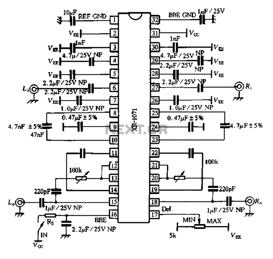
The 1071 touch utilizes audio enhancement technology, introducing a high-resolution two-channel stereo enhancement processing chip designed to improve product performance. It aims to enhance stereo sound systems, allowing various audio sources to exhibit a strong spatial presence. The chip...

TDA1510 is an audio power amplifier from Philips. This integrated circuit (IC) includes features such as load short protection, open load detection, and an overheat protection circuit. It offers stable output voltage, excellent ripple rejection performance, requires fewer external...

The TDA4863J basic application circuit operates with a positive supply voltage (VP), a flyback power supply voltage (VF), and a negative supply voltage (VN). The input signal is provided from the sawtooth signal input at pins 6 and 7,...
A collection of drawings showcasing various applications of the 555 timer IC. These include schematic diagrams sourced from online resources and literature, intended for personal reference. The original web pages from which these schematics were derived have not been...
The sensor operates on the principle that at high temperatures (200 to 800 °F), the temperature of the sensor varies with the thermal conductivity of gas, leading to changes in the resistance of the platinum resistor wire. In the...

This simple circuit can be used to flash incandescent lamps with a power rating of up to 10W. The circuit is ideal for creating flashing beacons on automobiles and similar applications. It consists of an astable multivibrator based on...