
Low Distortion Wien Bridge Oscillator
The Wien bridge oscillator is a type of electronic oscillator that generates sine waves. It is known for its ability to produce low-distortion outputs, which is essential in various applications, including audio signal generation and testing. The core of the oscillator consists of a bridge circuit that includes resistors and capacitors arranged in a specific configuration to set the frequency of oscillation.
In this particular design, the use of an incandescent lamp serves a dual purpose. Firstly, it acts as a variable resistor, whose resistance changes with the temperature. This property allows for automatic gain control, which stabilizes the amplitude of the output signal. As the amplitude of the oscillation increases, the lamp heats up, causing its resistance to rise and thereby reducing the gain. Conversely, if the amplitude decreases, the lamp cools down, lowering its resistance and increasing the gain. This feedback mechanism ensures that the output remains stable and minimizes distortion.
The circuit typically includes an op-amp configured as a non-inverting amplifier to provide the necessary gain. The frequency of oscillation can be adjusted by changing the values of the resistors and capacitors in the bridge circuit. This flexibility allows the oscillator to operate at multiple frequencies, making it suitable for various applications.
Overall, the incorporation of an incandescent lamp in the Wien bridge oscillator design enhances its performance by providing effective amplitude stabilization, resulting in a high-quality, low-distortion sine wave output across a range of frequencies.This Wien bridge oscillator uses incandescent lamp to stabilize its amplitude. This amplitude stabilization gives a low distortion output. Multiple frequency.. 🔗 External reference
Related Circuits
This simple and inexpensive crystal oscillator consists of one-third of a 7404 hex inverter, four resistors, and a crystal. The inverters are biased into their linear regions by resistors R1 to R4, while the crystal provides the necessary feedback....
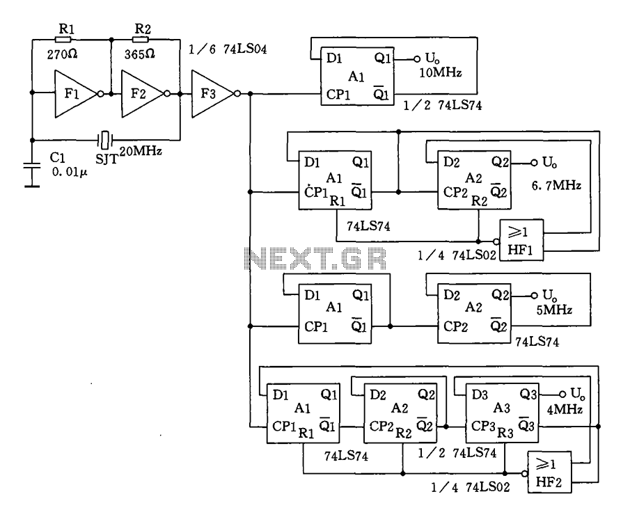
Crystal oscillator and frequency divider (74LS04) circuit diagram. The circuit diagram for a crystal oscillator combined with a frequency divider utilizing the 74LS04 integrated circuit is designed to generate a stable clock signal. The crystal oscillator component typically consists of...
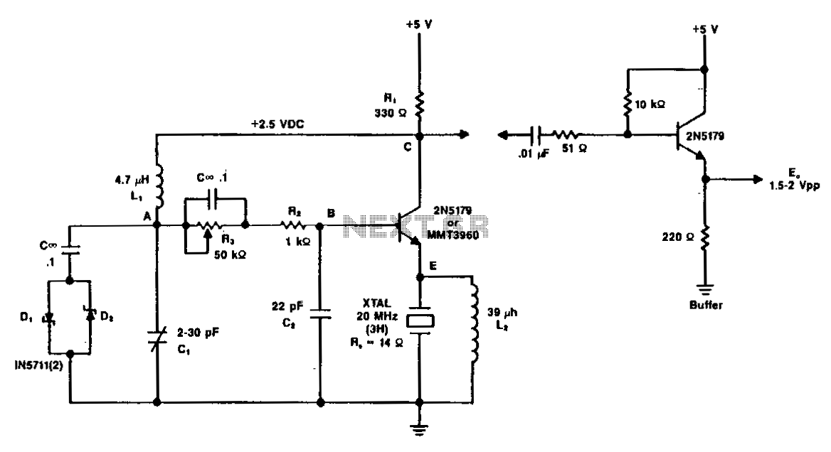
A typical circuit operating at 20 MHz is illustrated. The crystal, featuring an internal series resistance (Rs) of 14 ohms, oscillates at its third harmonic frequency. Diode clamps D1 and D2 ensure constant amplitude control. The transistor functions continuously...
The Colpitts oscillator circuit schematic is closely related to the shunt-fed Hartley oscillator, with the primary distinction being in the tank circuit design. In the Colpitts oscillator, two capacitors are utilized in place of divided coils. The basic feedback...
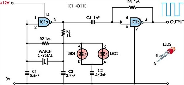
This circuit was designed to enable the use of watch crystals in an existing CMOS oscillator circuit powered by a 12V supply. The challenge arises because these crystals typically operate at a maximum supply voltage of approximately 6V; exceeding...
This circuit employs an HgCdTe demodulation device that can be cooled to 77K using liquid nitrogen. It utilizes a constant current bias for the demodulation device, which is connected to the input port. The voltage amplification factor is 200,...