Crystal oscillator and frequency divider 74LS04 schematic
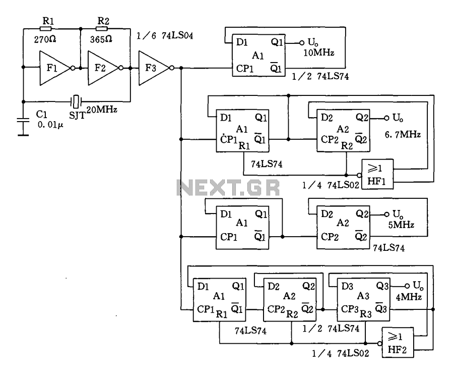
Crystal oscillator and frequency divider (74LS04) circuit diagram.
The circuit diagram for a crystal oscillator combined with a frequency divider utilizing the 74LS04 integrated circuit is designed to generate a stable clock signal. The crystal oscillator component typically consists of a quartz crystal, which is connected in parallel with the input of the inverter gates within the 74LS04. The inverter gates are used to create a feedback loop that enables oscillation at the crystal's resonant frequency.
In this configuration, the crystal is connected between the output of one inverter and the input of another, establishing a feedback mechanism that sustains oscillation. The frequency of oscillation is determined by the characteristics of the crystal and the associated passive components, such as capacitors, which may be connected to ground to stabilize the frequency.
The 74LS04 contains six inverters, allowing for multiple stages of frequency division if required. The output from the oscillator can be fed into additional inverters to achieve the desired frequency division. Each subsequent inverter stage effectively divides the frequency by two, resulting in a series of square wave outputs at frequencies that are halved with each stage.
The circuit's power supply should be connected to the Vcc pin of the 74LS04, while the ground pin should connect to the circuit's common ground. Proper decoupling capacitors should be placed close to the power supply pins to filter out noise and ensure stable operation.
This configuration is widely used in various applications, including clock generation for digital circuits, timers, and frequency modulation systems, due to its simplicity and reliability in producing precise frequency outputs.Crystal oscillator and frequency divider (74LS04) circuit diagram:
