
LOW DROPOUT THREE TERMINAL REGULATORS

When the power grid is lower than 220V, J1 normally closed contact changes the transformer B into boost type. If the output voltage does not exceed 220V, J2 normally closed contact connects to transformer 5 foot.
If it is higher than 220V, J2 pulls in and connects to transformer 4 foot. If the power grid is higher than 220V, it controls J1 to pull in by R1 sample, it is connected to transformer 5 foot, then it willform buck type. If output terminal voltage exceeds the set value, then to control J2 pull in by R4 sample, the normally open contact is connected to 4 foot.
The selection of components: regulator power depends on the transformer iron core section and enameled wire diameter. The iron chip can use 19G—(24 ½ 25), the coil adopts 0. 27~0. 35 high strength enamelled wire to close winding, it should not use packing paper between layers. 1~2 should go around 48 turns, 2~3 should go around 822 turns, from the third foot it uses 0. 41~0. 51 enamelled wire, 3~4, 4~5 all go around 85 turns. BG1, BG3 chooses 3DG small power tube, BG2, BG4 use PNP silicon middle power tube. There is no special requirements for resistance capacitance. (View) The functions of this circuit are: alarm, display, timing, digital display and temperature display.
MM5406 is the part of clock, it is PMOS IC, 40-foot packaging, its functions include: alarm, stop alarming, sleep, 12/24h time selection, second display, fast set h, slow set min, 50/60Hz clock selection. MM5407 is thermometer used IC, the temperature range is -40~+88ƒ, the temperature sensor uses LM334 or SL334, the temperature factor is 10mV/ƒ, it can be adjusted by W4.
This circuit has 9V spare battery. When the AC power is cut off, this battery is used as power supply, then the time clock works normally, but LED will be turned off due to the power failure. (View) As the diagram shows it is a practical infrared reflecting automatic lamp circuit. When you go closely to it, the lamp lights up. When you leave, the lamp goes out. It can be used for home storage room, bathroom lighting or dresser mirror front lamps and other occasions.
(View) As shown in the figure, circuit (a ) is an infrared light emitter circuit, the oscillation frequency is 20kHz; ( b) is an infrared light receiver circuit and K uses static power consumption memory self-locking relay ( DC5V ZS-01 ). (View) As shown in the figure for the automatic toilet lamp circuit, the lamp lights up when people come in and goes out when people go out.
At the same time the circuit also has a light control function. The circuit automatically block at daytime, the lamp doesn`t light. LED1, LED2 use PH303 type infrared emitting diode. (View) As the diagrams shows it is a automatic lamp with microwave radar TX982. Its feature is that the circuit will not be interfered by its own light and it is vey easy to be installed. It is suitable for washing room, storage room, dresser mirror light etc. It can realize the function that the lamp lights up when people come and it goes out when people leave.
(View) As the diagram shows, it is a automatic lamp which uses TWH9248/TWH9249 microwave emission and receiving sensor made in Guangdong Zhongshan Dahua electronics factory. It has the follow function: When the light at daytime or in room is strong, the lamp will not light up and when it is evening, t
🔗 External reference
Related Circuits
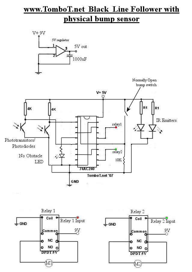
The motors will be powered by the full source voltage, so it is important to ensure that this does not cause the robot to operate too quickly. The Firebot utilizes GM3 motors powered by a 9V battery; however, in...
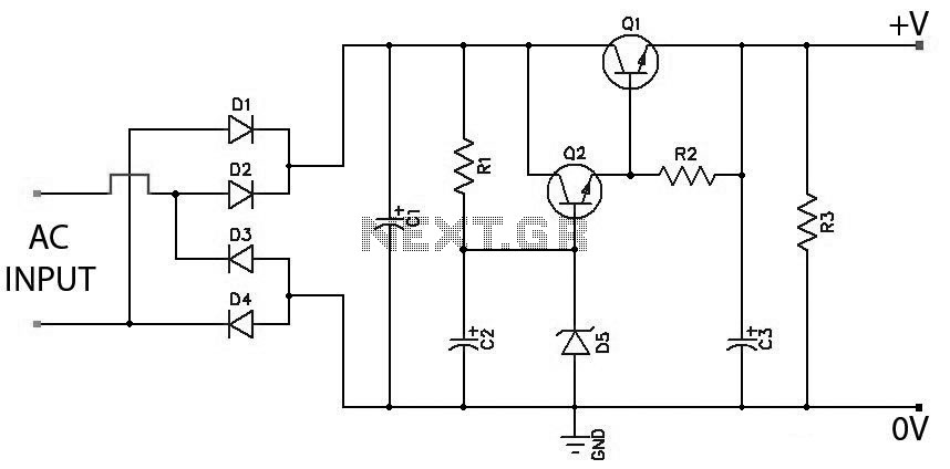
Low Ripple Regulated Power Supply Circuit Diagram. This circuit can be employed in applications requiring high current with minimal ripple voltage, such as in high-powered class AB amplifiers where high-quality audio reproduction is essential. The low ripple regulated power...
Power line fluctuations and cut-offs can damage electrical appliances connected to the line, particularly domestic appliances like refrigerators and air conditioners. When a refrigerator operates on low voltage, excessive current flows through the motor, leading to overheating and potential...
The RF engineer often needs an instrument that can reliably and quickly check a low-frequency quartz crystal unit. However, such equipment is challenging to find, and engineers frequently refer to electronic circuit handbooks for schematics that can perform this...
Assistance is required for converting high frequency to low frequency and vice versa. A project involving a sensor is currently in progress, and the schematic is provided below. The conversion of high frequency signals to low frequency signals, as well...
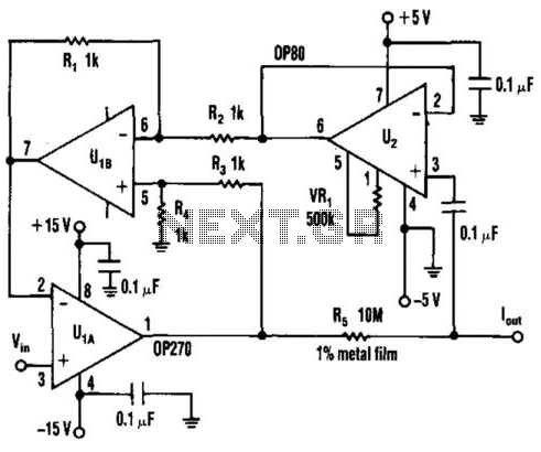
A current source that achieves a resolution as low as 10 pA is beneficial in applications requiring precise, low-value currents. When the circuit directs current into the ground, the output remains within 2% of the ideal current across the...