
Low frequency divider
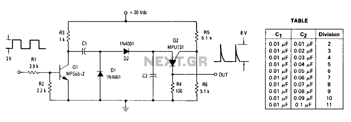
The described circuit employs capacitors C1 and C2 to create a voltage division mechanism influenced by the operation of a transistor Q1 and a Programmable Unijunction Transistor (PUT). The capacitors are initially in a discharged state, and when a positive pulse is applied to the base of Q1, both capacitors charge to a predetermined voltage, which is 10 volts in this scenario. The equal capacitance values of C1 and C2 facilitate a symmetrical charging and discharging process.
When Q1 is turned off, the capacitors undergo charging through resistor R3. The subsequent pulse at the base of Q1 causes C1 to discharge while C2 retains its charge. This sequence is crucial for the circuit's operation, as it allows C2 to reach the firing voltage of the PUT, leading to its activation. The firing of the PUT results in the discharge of C2, which in turn enables C1 to charge up to the line voltage, thereby creating a feedback loop that maintains the operation of the circuit.
The relationship between the input frequency and the capacitance values is critical for achieving the desired output frequency. The equation governing this relationship indicates that for a specific input frequency of 10 kHz and a voltage amplitude of 3 volts, certain capacitance values must be selected to ensure an effective division ratio, which is noted to be from 2 to 11 in the provided data. The operation of the circuit continues cyclically, with each cycle initiated by a positive pulse that prompts the discharge of C1, maintaining the overall functionality of the voltage division and timing mechanism.The ratio of capacitors Cl and C2 determines division. With a positive pulse applied to the base of Ql, assume that Cl = C2 and that Cl and C2 are discharged. When {31 turns off, both Cl and C2 charge to 10 volts each through R3. On the next pulse to the base of Ql, Cl is again discharged but C2 remains charged to 10 volts. As Ql turns off this time, Cl and C2 again charge. This time C2 charges to the peak point firing voltage of the PUT causing it to fire. This discharges capacitor C2 and allows capacitor Cl to charge to the line voltage. The input and output frequency can be approximated by the equation (Cl = C2) Cl For a 10 kHz input frequency with an amplitude of 3 volts, the table shows the values for Cl and C2 needed to divide by 2 to 11. As soon as C2 discharges and Cl charges, the PUT turns off. The next cycle begins with another positive pulse on the base of Ql which again discharges Cl. 🔗 External reference
Related Circuits
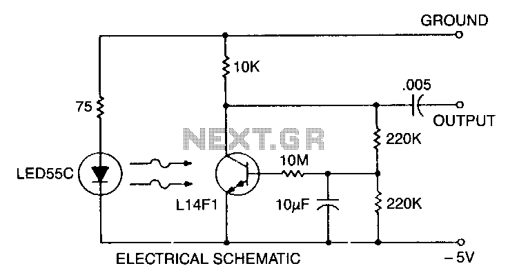
This self-biasing configuration is useful whenever small changes in light level must be detected, such as when monitoring very low flow rates by counting drops of fluid. In this bias method, the photodarlington is bias stabilized by feedback from...
This circuit is designed to power a laptop computer using a solar power setup. The computer requires 12V at 3.3A. The circuit employs a linear regulator with a MOSFET (Q4) as the series pass device. A 100kΩ resistor provides...
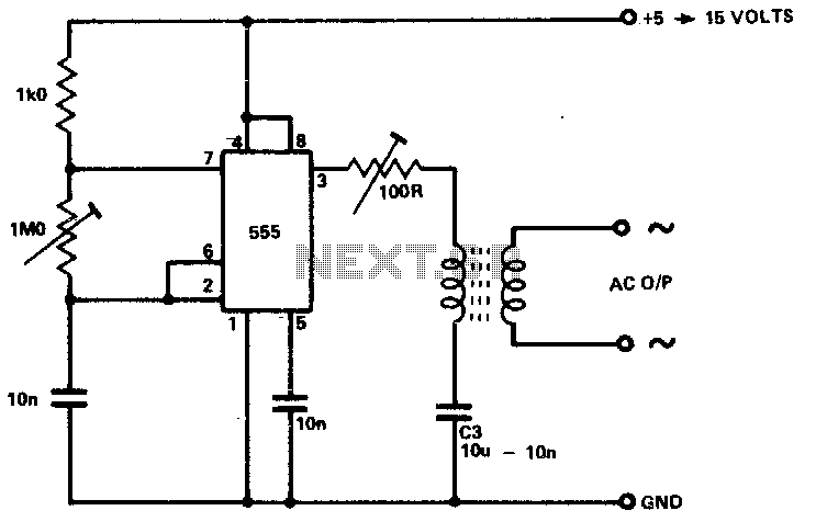
The circuit is designed to supply power for portable Geiger counters, dosimeter chargers, high resistance meters, and similar devices. The 555 timer integrated circuit (IC) operates in its multivibrator mode, with the frequency adjusted to optimize the characteristics of...
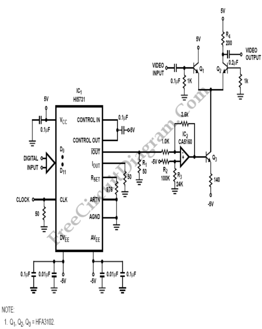
Variable-gain amplifiers (VGAs) can be used in many types of systems, such as radio receivers. In this system, the input signal voltage depends on an. Variable-gain amplifiers (VGAs) are integral components in various electronic systems, particularly in radio receivers where...
This circuit consists of a UJT oscillator where the timing charge capacitor C2 is linearly dependent on the input signal voltage. The charging current is determined by the voltage across resistor R5, which is precisely controlled by the amplifier....
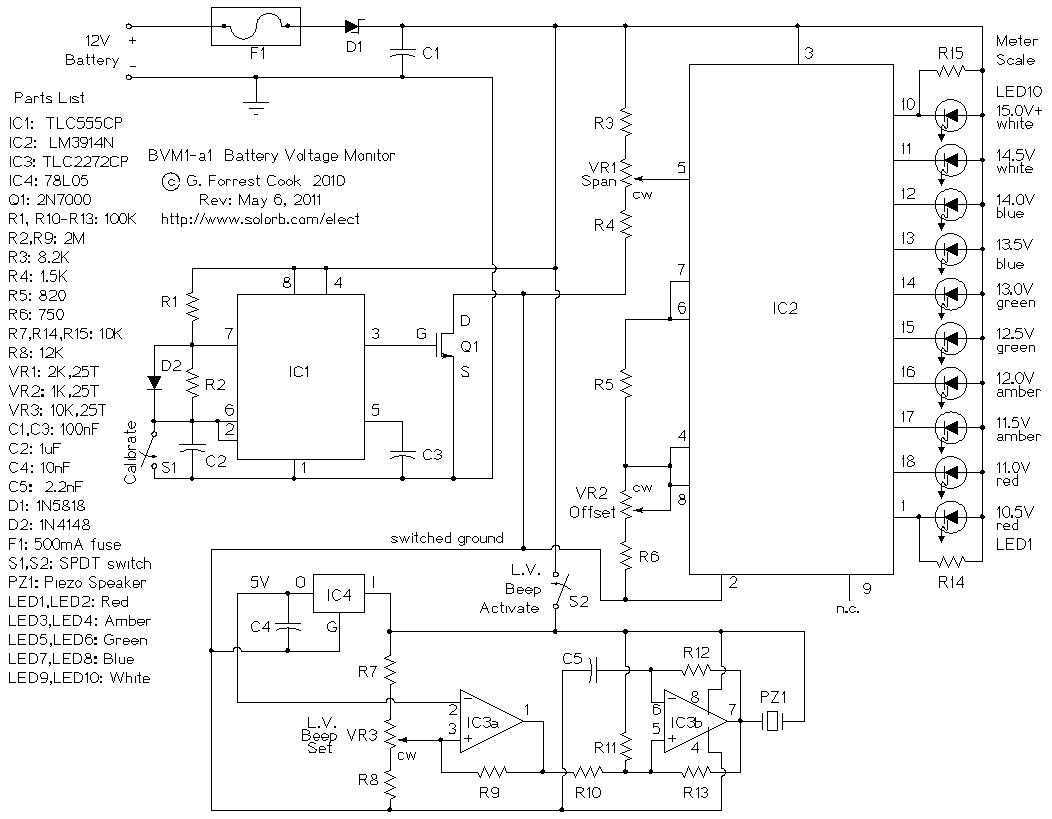
This circuit provides an audible and visual low voltage warning for 12V battery powered devices. When the battery voltage is above the set point (typically 11V), the circuit is idle. If the battery voltage should fall below the set...
Warning: include(partials/cookie-banner.php): Failed to open stream: Permission denied in /var/www/html/nextgr/view-circuit.php on line 713
Warning: include(): Failed opening 'partials/cookie-banner.php' for inclusion (include_path='.:/usr/share/php') in /var/www/html/nextgr/view-circuit.php on line 713