
Relay driver
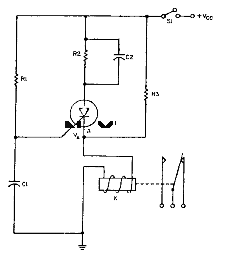
This circuit utilizes a relay controlled by a silicon-controlled rectifier (SCR) to manage timing functions. The initial delay, td, allows for a predetermined time before the relay engages, while the operational time, tc, defines how long the relay remains active. The SCR's triggering occurs when the voltage across capacitor Ci reaches the specified threshold voltage, VA, which is a critical parameter for ensuring proper operation of the relay.
Upon activation, the relay will remain engaged until the current flowing through capacitor C2 decreases to a level below the dropout current. This behavior is essential for applications where maintaining the relay in an energized state is crucial. If continuous operation is desired, capacitor C2 can be omitted from the circuit, and the value of resistor R2 must be carefully chosen. R2 must be sufficiently large to allow the relay coil current to stay within its operational limits without exceeding the maximum ratings.
The component values provided are designed to achieve specific timing characteristics. With R1 set at 1.5 megohms, the circuit can achieve a delay of 30 seconds. Meanwhile, R2 and R3 are set at 10 k ohms and 3 k ohms, respectively, to ensure the relay operates correctly within the required time frame. Capacitors C1 and C2 are chosen as 47 µF and 100 µF, respectively, to facilitate the necessary charging and timing functions.
The SCR selected for this circuit, the 2N1877, is suitable for switching applications that require precise control over timing and current flow. The relay, a Potter Brumfield PW-5374, is capable of handling the required load and provides reliable operation in various applications. The assumed supply voltage of 12 Vdc is typical for many control systems, ensuring compatibility with standard power sources while allowing for efficient operation of the relay and associated components.The relay operates a certain time, td, after power is applied to it, and then it operates for a length of time, tc. The SCR fires when the voltage on Ci reaches VA. This operates the relay, which stays activated until the current charging C2 drops below the dropout current.
To keep the relay in its activated position indefinitely (tc =00), eliminate C2 and choose R2 just large enough to keep the relay coil current within its related limits. Typical component values for td = 30 seconds and tc = 2 seconds are: Rl = 1.5 megohms, R2 = 10 k ohms, R3 = 3 k ohms, Cl = 47 µ¥, and C2 = 100 µ¥. The SCR is a 2N1877 and the relay is a Potter Brumfield PW-5374. A value of 12 Vdc is assumed for V~. 🔗 External reference
Related Circuits
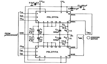
The diagram below illustrates a Two Phase Bipolar Stepper Motor Driver utilizing the PBL3717A. It depicts two PBL3717A integrated circuits (ICs) that control and drive two bipolar stepper motors. The Two Phase Bipolar Stepper Motor Driver circuit is designed to...
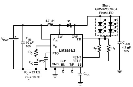
The LM3551 and LM3552 are fixed frequency, current mode step-up DC-DC converters featuring two integrated NFETs. These devices facilitate the design of a straightforward and highly precise LED brightness control system. They are capable of driving loads up to...
A simple thermostat circuit can be utilized to control a relay, which in turn supplies power to a small space heater via the relay contacts. It is essential that the relay contacts are rated above the current requirements for...
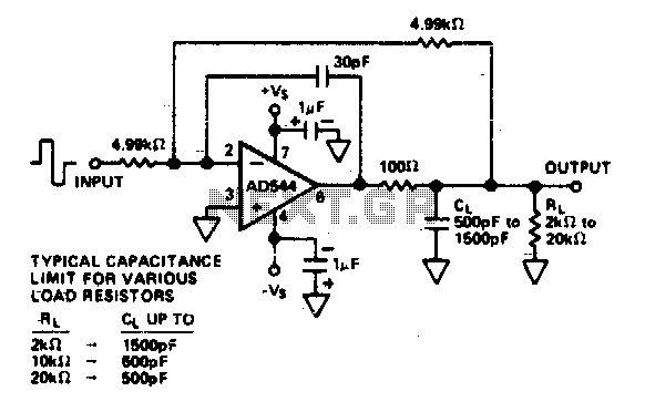
The circuit utilizes a 100-ohm isolation resistor that allows the amplifier to drive capacitive loads greater than 500 pF. This resistor effectively isolates high-frequency feedback from the load, contributing to circuit stability. Low-frequency feedback is returned to the amplifier's...
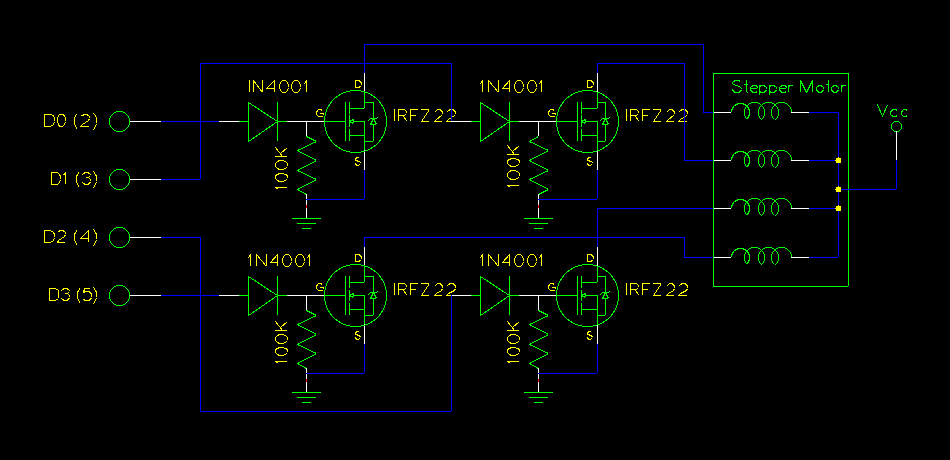
The use of a PC's parallel port provides a convenient method for controlling a stepper motor. For unipolar stepper motors, it is possible to control up to two motors using the 8-bit data line. Typically, a Darlington driver, such...
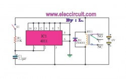
The function of this circuit is to prevent equipment damage caused by pressure and to provide a delay for other appliances connected to the output of the relay. The circuit includes components such as a 4011 IC, a diode,...