
l293d motor driver
The L293D is an integrated circuit designed for driving DC motors and stepper motors, providing a convenient interface between low-power control signals and high-power motor operations. The chip features dual H-bridge outputs, allowing for bidirectional control of two motors or control of a single motor at different speeds and directions.
In the schematic, the L293D is typically represented with its power pins connected to a suitable power supply, which can be higher than the logic level voltage. The Vcc pin connects to the motor power supply, while the Vss pin connects to the logic supply, typically +5V. The enable pins (1 and 9) must be activated to allow the motor outputs to function, usually connected to the logic high level.
The input pins (2, 7, 10, and 15) receive control signals from a microcontroller or other logic devices, determining the direction and speed of the motors. When one of the input pins is set high while the corresponding enable pin is activated, the associated output pin drives the motor in one direction. Conversely, driving the opposite input pin high reverses the motor's direction.
Decoupling capacitors are often placed close to the power pins to filter out noise and prevent voltage spikes from affecting the performance of the L293D. Additionally, flyback diodes may be included in the schematic to protect the circuit from voltage spikes generated when the motors are switched off, which could otherwise damage the L293D.
For applications requiring multiple motors or higher current ratings, multiple L293D chips can be paralleled, ensuring that each motor receives sufficient power while maintaining operational integrity. Proper thermal management, such as heat sinks, may be necessary due to the power dissipation in the chip, particularly under heavy load conditions.
In summary, the L293D schematic provides a robust framework for motor control applications, balancing power requirements and control flexibility while mitigating potential interference and ensuring reliable operation.L293D Schematic diagram. L293D division provides power for the chip and its controlled motors, allowing you to connect motors with high-voltage power supply than the chip. The separation of power circuits and electric motors may also be necessary to reduce interference caused by the Surge, work-related motors.
🔗 External reference
Related Circuits
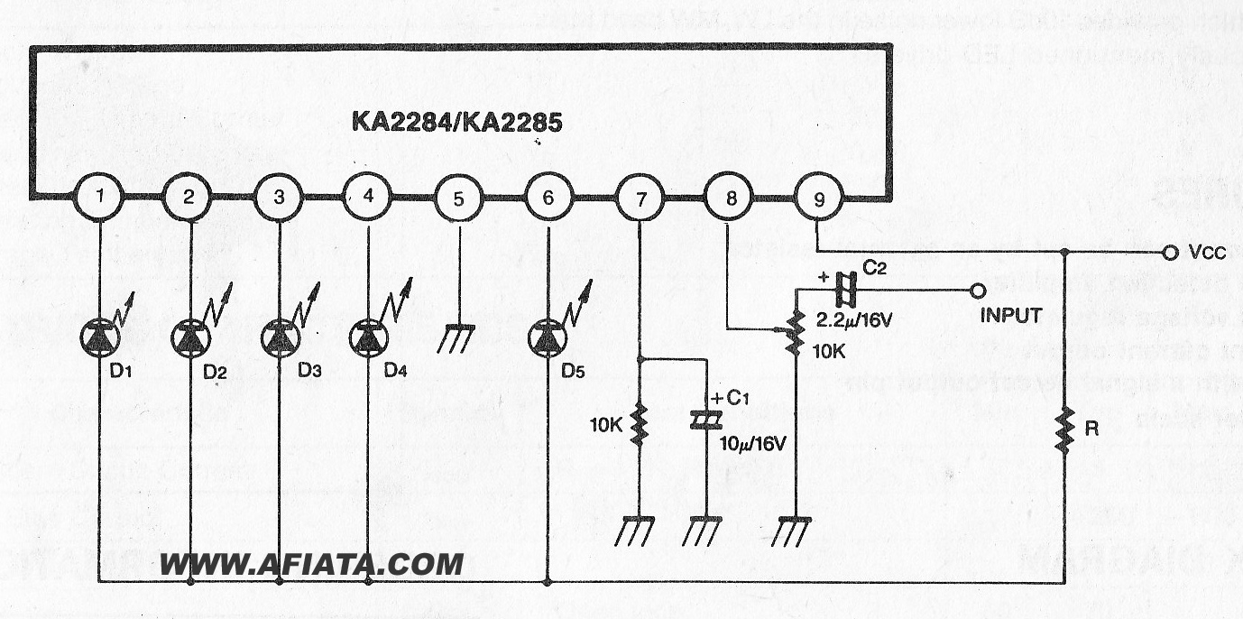
The KA2284 is a monolithic integrated circuit designed for 5-dot LED level meter drives with a built-in rectifying amplifier. It is suitable for both AC and DC level meters, such as VU meters or signal meters. The KA2284 integrated circuit...
The L29 Stepper Motor Controller IC facilitates the control of four drive signals for two bipolar and four unipolar footfall motors in a microcomputer-controlled appliance. It allows for motor operation in half-step, full-step, and wave drive modes, utilizing switch-mode...
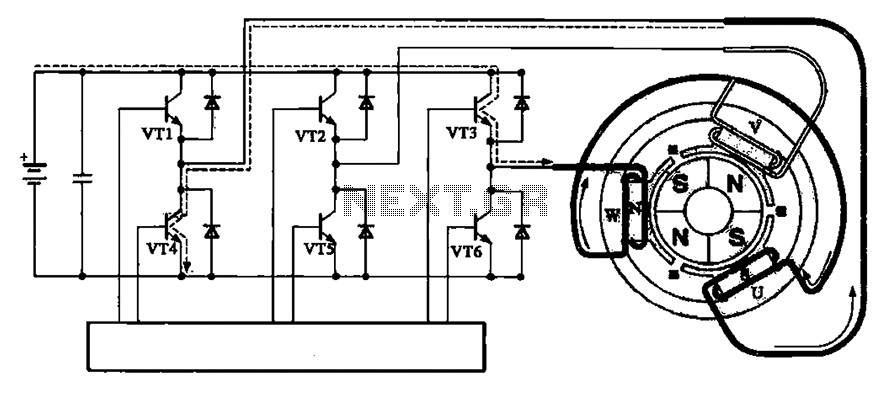
The brushless motor consists of a rotor, a stator, and a drive circuit. The relationship between the brushless motor rotor, stator, and drive circuit is illustrated in the accompanying figure. In the initial state, VT3 and VT4 are conducting,...
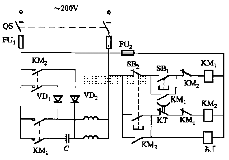
The circuit depicted in Figure 3-150 involves a contactor (KM1) that releases when the system is shut down. The contactor KM2 is energized, allowing a 220V AC power supply to flow through diodes VD1 and VD2, which serve as...
This circuit controls a small, four-phase, five-wire, unipolar stepper motor, commonly designated as the "KP4M4-001." This type of motor was utilized in many 5 1/4" floppy disk drives in older computers. Although now obsolete, such disk drives are often...
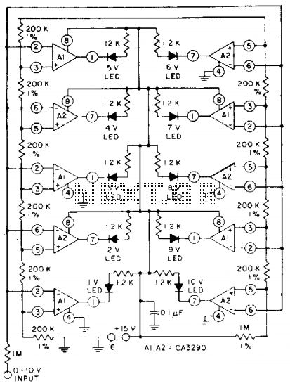
The circuit utilizes CA3290 BiMOS dual voltage comparators. The non-inverting inputs of A1 and A2 are connected to a voltage divider reference. The input signal is applied to the inverting inputs. LEDs are activated when the input voltage reaches...