
Low impedance microphone amp
The described circuit functions as a microphone amplifier specifically designed for low impedance microphones, typically around 200 ohms. It operates effectively within a voltage range of 9 to 30 VDC, which allows for flexibility in various applications, from professional audio equipment to DIY projects.
The circuit includes an impedance adapter, which is represented by the transformer T1. This component is crucial for adapting the input signal from low impedance microphones to a level suitable for amplification. If the impedance adapter is omitted, the circuit can still serve as an amplifier for higher impedance microphones. In this scenario, the audio signal should be directly connected to capacitor C7, which serves as a coupling capacitor, blocking any DC component while allowing the AC audio signal to pass through to the subsequent amplification stage.
The overall design may include additional components such as resistors and capacitors to set gain levels, filter unwanted frequencies, and stabilize the circuit operation. The output of the microphone amplifier can be connected to various audio processing equipment, such as mixers or audio interfaces, ensuring compatibility across different systems. Proper layout and grounding techniques should be employed to minimize noise and interference, which is critical in audio applications.The circuit is a microphone amplifier for use with low impedance (~200 ohm) microphones. It will work with stabilized voltages between 9-30VDC. If you don`t build the impedance adapter part with T1, you get a micamp for higher impedance microphones. In this case, you should directly connect the signal to C7. 🔗 External reference
Related Circuits
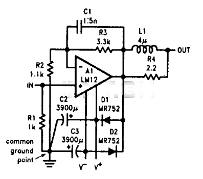
Output-clamp diodes are essential due to the inductive nature of loudspeakers. Output LR isolation is employed as audio amplifiers are typically designed to manage load capacitance of up to 2 µF. Large supply-bypass capacitors placed near the integrated circuit...

Designed for self-powered 8, 4 & 2 Ohm loudspeakers. This amplifier was designed to be self-contained in a small loudspeaker box. It can be fed by Walkman, Mini-Disc, iPod and CD players, computers and similar devices fitted with line...
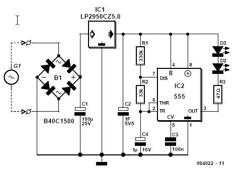
This article is relevant only to readers whose bicycle lights are powered by a dynamo. The regulations regarding bicycle lights in the United Kingdom are stricter than those in other regions. Dynamo-powered bicycle lights utilize a generator that converts mechanical...
Originally posted by ide2003, the message suggests that if one wishes to avoid using an operational amplifier (op-amp) entirely, it is highly recommended to consider ECDesign. The mention of avoiding op-amps in circuit design indicates a preference for alternative methods...
A compact 325mW amplifier with a voltage gain of 200, suitable for use as a bench amplifier, signal tracer, or to amplify the output from personal radios. The circuit utilizes the National Semiconductor LM386 amplifier. In the schematic, the...
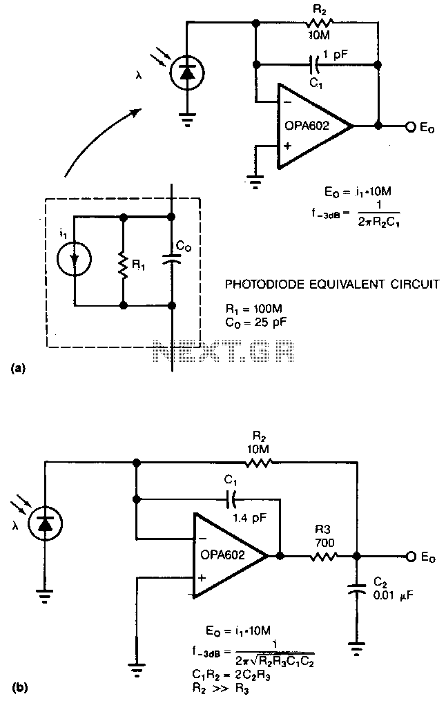
Adding two passive components to a standard photodiode amplifier reduces noise. Without the modification, the shunt capacitance of the photodiode reacting with the relatively large feedback resistor of the transimpedance (current-to-voltage) amplifier creates excessive noise gain. The improved circuit...