
ATTiny Joule Thief circuit
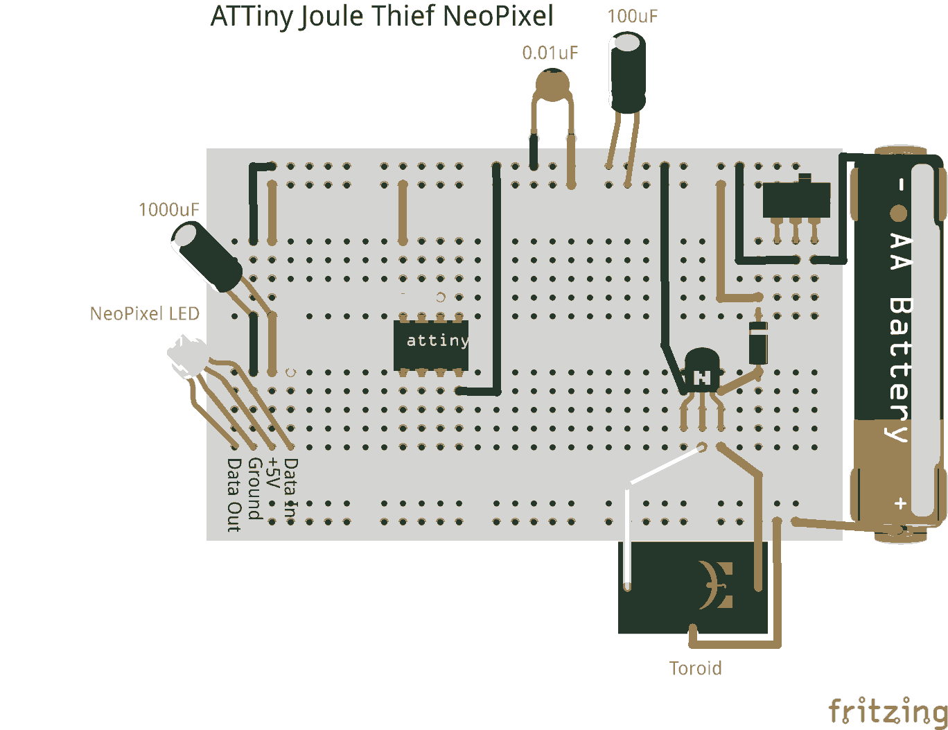
Joule thieves are simple and efficient circuits designed to extract and boost low voltage energy from sources such as depleted batteries to power small electronic devices. The incorporation of an ATtiny microcontroller enhances the functionality of a Joule thief by allowing for more complex control and modulation of the output, making it suitable for powering addressable LED strips like NeoPixels.
In a typical setup, the circuit consists of an inductor, a transistor, a resistor, and a diode. The inductor stores energy when the transistor is in the off state and releases it when the transistor turns on, boosting the voltage to a level sufficient to power the NeoPixel LEDs. The ATtiny microcontroller can be programmed to manage the timing and switching of the transistor, allowing for various lighting effects and patterns.
This setup can be particularly advantageous in applications where energy efficiency is crucial, such as in remote or battery-operated devices. By utilizing the low power consumption of the ATtiny alongside the Joule thief circuit, it is possible to achieve longer operational times from minimal power sources, while also providing the vibrant colors and effects offered by NeoPixel technology.
Overall, the combination of a Joule thief circuit with an ATtiny microcontroller represents a versatile solution for driving low-voltage LED applications, expanding the possibilities for creative electronic designs.Joule thieves arent just for lighting plain old LEDs!. Attiny joule thief neopixel 🔗 External reference
Related Circuits
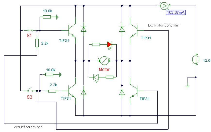
This is a DC motor controller circuit built using the TIP31 transistor based on the H-Bridge concept. The switches S1 and S2 are normally open, push-to-close buttons. The LED serves to indicate the direction of motor rotation and any...
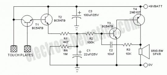
Touch the sensor of the alarm with your finger, and it starts beeping. It continues for a period and then stops. Touching it again will activate the beeping once more. This description outlines a basic touch-activated alarm system. The...
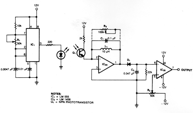
Dark Activated Switch or Porch Light Switch. This circuit activates a relay when the light level drops below a preset threshold. The light sensitivity can be adjusted using variable resistor VR1, and the relay contacts can control an external...

The circuit depicted here is designed to identify defective bulbs by capacitively sensing the electric fields they generate. To understand its operation, consider a string of bulbs with an open-circuited filament, referred to in the schematic as the String...

This design circuit functions as an alarm system controlled by a keypad. The core component of the circuit is a single transistor from the BC547 series. The circuit requires a 12-key pad, which has 13 terminals; a matrix type...

The alarm circuit operates as follows: When the power switch SW1 is turned on, the alarm system becomes active. If a magnet is brought close to the spring, the magnetic field attracts the spring, causing the dynamic and static...