
Signal Generator circuit
The described circuit focuses on evaluating the performance of different operational amplifiers in terms of harmonic distortion, specifically second and third harmonics. The op-amps selected for this comparison—TL072, LM4562, and OPA2134—represent a range of technologies and specifications. The testing setup involves a feedback network with a 500k potentiometer, allowing for adjustments in feedback levels to observe their impact on harmonic distortion.
The circuit employs a twin-T filter configuration, which is known for its effectiveness in audio applications. The choice of op-amps is critical, as their characteristics directly influence the distortion profile of the output signal. The TL072, despite being an older design, demonstrates competitive performance, while the LM4562 shows unique behavior with its unexpected harmonic content. The OPA2134 emerges as a suitable candidate for this application, balancing performance with layout considerations.
Powering the circuit with 9V rechargeable batteries eliminates potential interference from mains power, emphasizing the importance of circuit layout and component placement in minimizing distortion. The inclusion of bypass capacitors, particularly the 100nF capacitor between the op-amp supply pins, is a common practice aimed at enhancing stability and reducing noise.
In terms of feedback manipulation, the adjustments made to the 220-ohm resistor and the 500k potentiometer provide insights into the relationship between feedback levels and harmonic distortion. The findings indicate that op-amp distortion is a significant contributor to the second harmonic, while the lamp used in the circuit may introduce additional harmonic content.
Overall, this evaluation highlights the complexities involved in optimizing audio circuits for low distortion. The results underscore the need for careful component selection, layout considerations, and an understanding of the interactions between various elements within the circuit to achieve the desired performance characteristics.The output level was set to 3. 8V peak to peak, not for any good reason, the first aim was to compare a few different op-amps before trying to further optimise the circuit. The op-amps were TL072, LM4562 and OPA2134. The distortion spectra are shown next, in all cases the 500k feedback level control was set to maximum resistance.
Clearly this is not the maximum value allowing oscillation, so some further improvement should be possible. For later tests the 5k6 shown with a dotted connection was added. These were not entirely what I had expected. The TL072 is rather ancient, but even so was not far behind the two `ultra-low distortion` types. Used as an inverting amplifier most op-amps perform reasonably well at 1kHz. All three op-amps produced more second harmonic than third. The most baffling result however is the LM4562, which appears to have the lowest 2nd and 3rd harmonics, but has additional components at very close to 100Hz intervals. The board is powered from 9V rechargeable batteries, so it is not a mains supply frequency problem. I had thought there may be some stability problems with this op-amp, its 55MHz gain-bandwidth specification is worrying, and suggests far more care is needed with layout.
I built the circuit on a piece of veroboard, but included the sometimes recommended 100n capacitor between the op-amp supply pins. I can easily believe that layout is the cause of the problem, but why there would be frequency components at almost exactly 100Hz intervals remains a mystery, there was nothing obvious at 100Hz to cause an intermodulation effect.
Anyway, not wanting to spend much time trying to solve that problem I decided to stick with the OPA2134. Its more modest 8MHz gain bandwidth is maybe more compatible with my seriously sub-optimum experimental layout.
Looking at the data sheet for another ultra-low distortion op-amp, the LME49990, supply bypassing using three parallel capacitors with different values and dielectrics is suggested, for reasons not explained other than being `from experiment`. I have occasionally in the past used parallel capacitors without much thought, but having concluded that this serves no useful purpose and abandoned the practice I would have liked to see some theoretical justification.
There is some evidence of potential problems with parallel resonances when parallel capacitors of different values are used, e. g. see here. Choosing a single supply bypassing capacitor of a few uF with leads close together and as short as possible to minimise series inductance is my approach for most audio applications.
Using the OPA2134, by adjusting the 220R in the twin-T the 3rd harmonic could be reduced to -120dB relative to the 1kHz fundamental, but the 2nd harmonic changed very little. Reducing the 500k feedback level control the 3rd increased far more than the 2nd. The obvious conclusion is that the 2nd harmonic is op-amp distortion, and the 3rd is from the lamp. The lamp could also add some 2nd harmonic if there is a dc component applied to it, but there should only be a very low level of dc resulting from the op-amp offsets.
Op-amp distortion could be a real problem because of the relatively low supply voltage and the loading effect of the twin-T filter. Even so the 2nd harmonic is higher than I would expect from the op-amp specifications. The OPA2134 data sheet does show the relative levels of 2nd and 3rd, with the 2nd significantly higher.
There are a few non-harmonic components, e. g. around 4. 3kHz, but no screening box was used during these tests, so with a metal case this should be much improved. Further attenuation of the feedback through the 500k preset by adding a 5k6 to earth at the junction with the 56k resistor confirmed that the feedback needed for oscillation could be reduced much further, and the preset could still be set to its maximum resistance, at which point the 3rd harmonic had disappeared from view, somewhere
🔗 External reference
Related Circuits
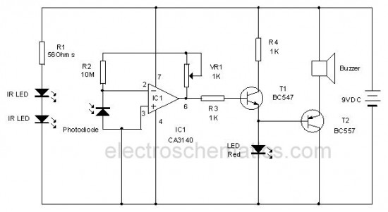
This circuit utilizes invisible infrared light to detect the movement of individuals passing through a doorway. A short beep is produced when the infrared beam is interrupted. The circuit operates by employing an infrared transmitter and a receiver. The transmitter...
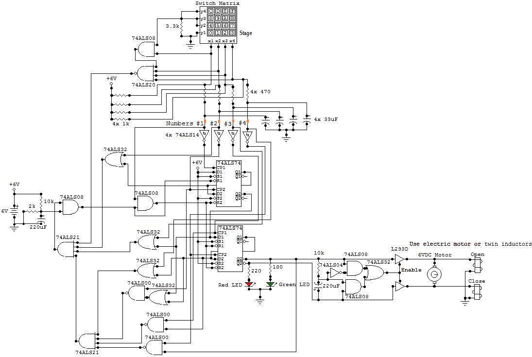
This circuit is an electronic locker controlled by a combination of switches (a code). It features a switch matrix located on the locker door, consisting of a unit of switches arranged in four rows and four columns, totaling eight...
The circuit in Figure 1 converts pulse information to a clean dc voltage by the end of a single incoming pulse. In another technique, an RC filter can convert a PWM signal to an averaged dc voltage, but this...
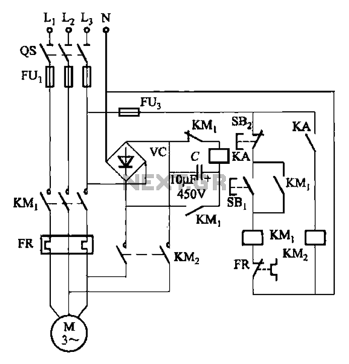
The circuit depicted in Figure 3-137 eliminates the need for a step-down transformer by utilizing the principle of energy storage capacitor discharge for braking. It can be employed to transform the power of motors with a rating of less...
This time, we will share information about Yo3dac's homebrew RF circuit design ideas, including the latest updates from Onmilwiki. Yo3dac is known for innovative approaches in the realm of radio frequency (RF) circuit design, particularly within the homebrew community. The...
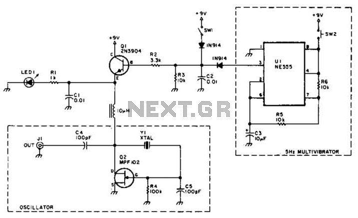
A useful marker oscillator can be constructed using an NE555 timer to generate pulses at an audio frequency. This design facilitates the detection of the signal even amidst interference. The crystal frequency can range from 1 to 30 MHz. The...