
Low-pass filter
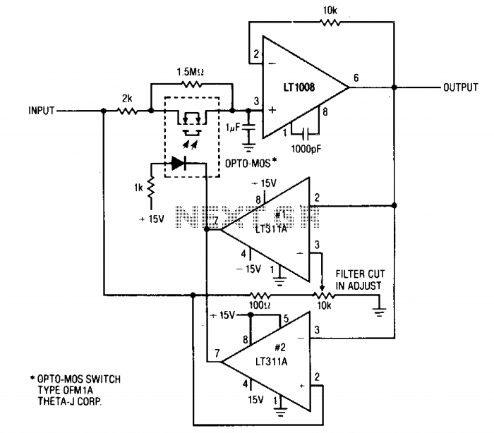
This circuit is designed for applications demanding rapid signal processing and high accuracy, particularly in the context of electronic weighing systems. The initial configuration employs a 2-ohm resistor in conjunction with a 1 µF capacitor to create a low-pass filter with a specific time constant, which governs the response time of the circuit until comparator No. 1 engages. The time constant, defined as τ = R × C, results in a response time that allows for quick signal acquisition.
Upon activation of comparator No. 1, the circuit transitions to a secondary configuration where a 1.5-ohm resistor and a 1 µF capacitor replace the initial components. This modification further enhances the speed of the circuit, allowing it to stabilize at a final output value significantly quicker than a standard filter setup with the same capacitance but a higher resistance value, such as the 1.5-ohm and 1 µF combination. The circuit's design minimizes DC error, ensuring that the output closely reflects the actual input signal without significant drift or offset.
Additionally, comparator No. 2 plays a crucial role in the circuit by providing a rapid reset function. This feature is essential for applications where continuous operation and quick recovery from transient states are necessary. The overall performance of this circuit makes it highly suitable for precision measurement devices, where both speed and accuracy are critical parameters. The design considerations and component selections reflect a careful balance between response time and signal fidelity, resulting in an effective solution for high-performance electronic scales.This circuit is useful where fast signal acquisition and high precision are required, as in electronic scales. The filter's time constant is set by the 2 ohm resistor and the 1 µ capacitor until comparator No. 1 switches. The time constant is then set by the 1.5 ohm resistor and the 1 jtF capacitor. Comparator No. 2 provides a quick reset. The circuit settles to a final value three times as fast as a simple 1.5 ohm—1 µ¥ filter, with almost no dc error. 🔗 External reference
Related Circuits
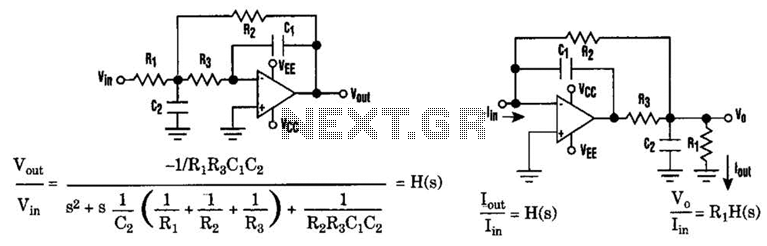
The low-pass Sallen-Key filter is a staple for designers because it contains few components. By redesigning the filter, a current-to-voltage conversion can be avoided when the input signal to be filtered is in current form. The Sallen-Key filter is a...
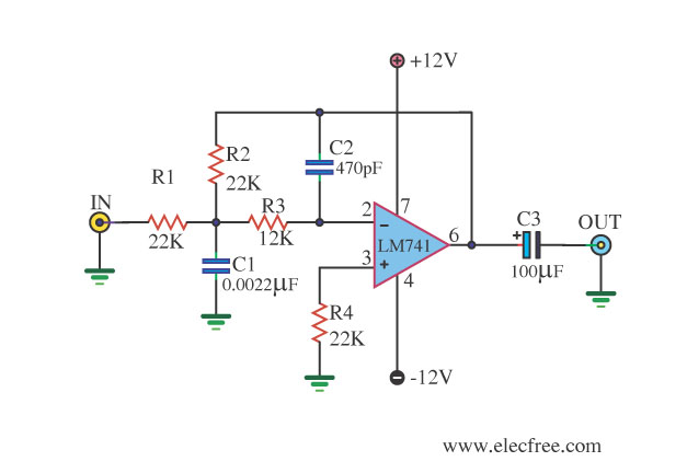
This circuit filters low frequencies below 10 kHz using the highly popular operational amplifier IC uA741. It is convenient for applications that require the conversion of analog signals to digital or vice versa. In digital sound systems, this circuit...
The purpose is supposedly to account for the fact that human hearing is less sensitive at low and high frequencies than in the upper midrange, and that this variation is dependent upon the sound intensity (SPL). The Fletcher-Munson curve...
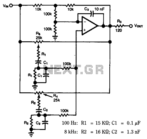
Most audio tone controls affect midband gain and often create booming or hissing sounds when activated. These problems can be avoided by using a dual Wien-bridge filter to provide independent control of the treble and bass frequencies. Experiments with...
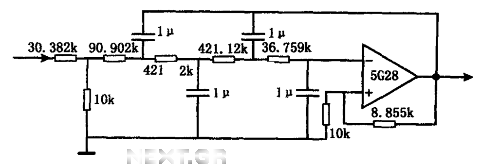
The circuit illustrated in the figure represents a staggered low-frequency active filter. This is a fourth-order Butterworth low-pass active filter designed to filter very low frequency (VLF) random pulse noise voltage at the DC level. The cut-off frequency is...
These are operational amplifier (op-amp) based filters that are particularly effective within the audio frequency range. The calculators for these filters utilize formulas and tables from the book "Electronic Filter Design Handbook" by Arthur B. Williams. Bandpass filters allow...