
Robots Bandpass Filter Calculator

Users can specify the desired capacitor values, with all capacitors in the circuit being identical and ideally having a tolerance of 1%. For midrange audio frequencies, a starting capacitor value of 0.01 µF is recommended. It is important to note that narrow bandwidth filters necessitate tighter component tolerances compared to wideband filters. The desired voltage gain can be entered, which represents the ratio of output to input voltage, not in dB. If a gain exceeding the circuit's capability is selected, an "ERROR" message will appear in the output data values. The maximum gain is contingent on bandwidth and the number of sections. After clicking "COMPUTE," the resistor values will be displayed. If the values are not optimal, users are encouraged to try different capacitor values and recompute. For optimal performance, 1% tolerance resistors should also be utilized. Additionally, the Q factor and center frequency for each filter section are computed. If the Q factor is excessively high, the component values will become very critical, and the op-amp may require enhanced performance. Reasonable Q values are typically up to about 20; exceeding this may lead to circuit instability.
The center frequency for each section can be adjusted by varying R2 (or R5 or R8), with frequency increasing as resistance decreases. The provided circuits assume the use of classic dual supply op-amps that require both positive and negative power, such as the LM348. In cases where a single supply op-amp (e.g., LM324) is used, it is necessary to connect the grounds (R2, R5, and the positive op-amp inputs) to a virtual ground, which is typically positioned halfway between real ground and Vcc. This can be achieved by connecting two 1K resistors in series between Vcc and ground, with a 10 µF capacitor connected from the junction of the two resistors to ground. The junction of these resistors serves as a virtual ground at Vcc/2. An example of this setup is available, demonstrating a high pass filter, although the underlying principle remains consistent. Single supply quad CMOS op-amps, such as the LMC660 or LMC6484, are often preferred due to their rail-to-rail output swing and wide bandwidth characteristics. The dual version of these op-amps is the LMC6032.
These operational amplifier-based filters provide a versatile solution for audio applications, allowing for precise control over frequency response characteristics while accommodating various design constraints.They are op-amp based filters and are most useful in the audio frequency range. These parts calculators are based on formulas and tables from the book " Electronic Filter Design Handbook " by Arthur B. Williams. Bandpass filters pass a contiguous range of frequencies while attenuating those above and below the passband.
The calculators compute parts values for both 4 and 6 pole multiple-feeback bandpass (MFBP) filters. Click here for a tutorial on Bandpass filters. Paul Falsted has a great online interactive Java program to help visualize filter responses with different poles and response types. Use it to see how a particular filter will perform. Select the desired filter type from the drop down menu. Butterworth is optimized for flat frequency response in the pass band. Chebyshev sacrifices flatness for a steeper roll off in the stop band. This version has 0. 1 dB of passband ripple. Bessel filters sacrifice both flatness and roll off for linear phase in the pass band. Select the desired value for the capacitors. All the capacitors in the circuit are identical and for best results should be 1% tolerance. For midrange audio frequencies 0. 01 uF is a good starting point. Note: Narrow bandwidth filters require tighter component tolerances than wide band filters. Enter the desired voltage gain. This the the ratio of the output to input voltage, not dB. If you select a gain higher than the circuit can deliver you will see "ERROR" in the output data values.
Max gain will vary depending on bandwidth and number of sections. Click COMPUTE and read the resistor values. If the values are not optimum try a different capacitor value and try again. For best results use 1% tolerance resistors. Also computed are the Q and center frequency of each section of the filter. If the Q is too high parts values will be very critical and the op-amp will require higher performance. Q values up to about 20 are reasonable. Above that may result in an unstable circuit. Note: The center frequency of each section can be adjusted by varying R2 (R5 or R8). Frequency goes up as resistance goes down. The circuits below assume classic dual supply op-amps that use plus and minus power such as the LM348.
If you use a single supply op-amp (eg: LM324 ) you will need to connect the grounds (R2, R5, +op-amp inputs) to a virtual ground, usually half way between real ground and Vcc. One way to do this is connect two 1K resistors in series between Vcc and ground. Connect a 10uF capacitor from the junction of the two resistors to ground. The junction of the two resistors is a virtual ground at Vcc/2. Click here for an example. It`s for a high pass filter but the principle is the same. I like to use single supply quad cmos op-amps such as LMC660 or LMC6484 because of their rail to rail output swing and wide bandwidth.
The dual version is LMC6032. 🔗 External reference
Related Circuits
A 183.6 MHz SAW filter is utilized in a CDMA application. The S-parameter of the SAW filter is employed to simulate the interaction with the mixer. An example is provided using the SAWTEK 855893 SAW filter. This application note...
This active subwoofer filter circuit is a 24 dB per octave filter with a Bessel characteristic and a cutoff frequency of 200 Hz. It is suitable for those experimenting with audio circuits in the subwoofer range, as all audio...
A bridge rectifier module is strongly recommended over building a bridge rectifier circuit using individual diodes. These modules are designed to be mounted on a metal heat sink. A metal enclosure is preferred over a plastic one due to...
By using transformers, both voltage feedback and current feedback can be applied. An article by DJ2LR Ulrich Rohde in Ham Radio, November 1979, provides details about this circuit. For the 2.5 MHz to audio converter, the transformation ratio from...
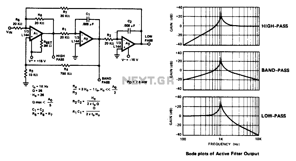
The active filter is a state variable filter with bandpass, high-pass, and low-pass outputs. It is a classical analog computer method of implementing a filter using three amplifiers and only two capacitors. The state variable filter is a versatile circuit...
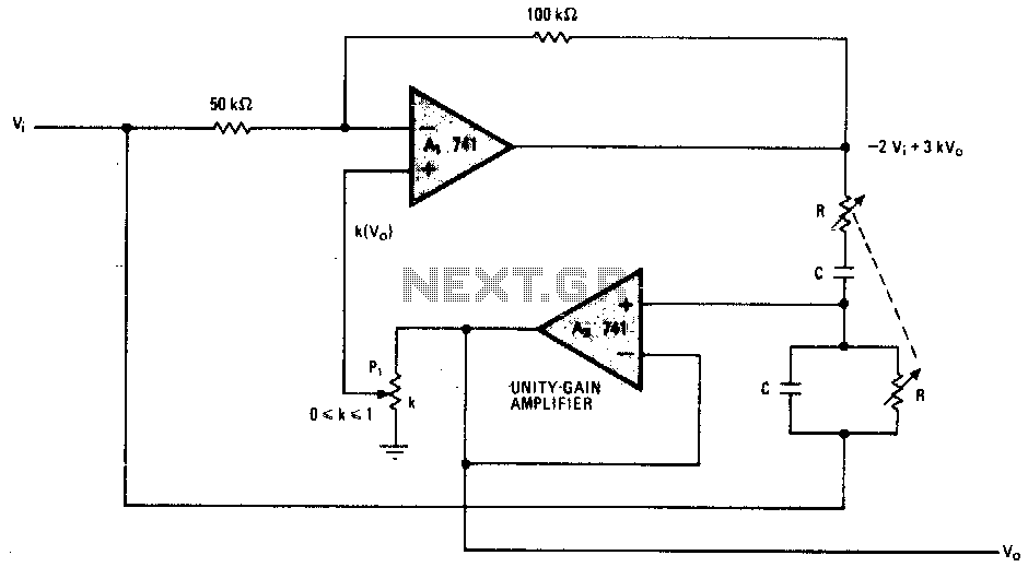
This notch filter operates at frequencies up to 200 kHz and utilizes a modified Wien bridge to select the center frequency. The PI component determines the notch bandwidth, which defines the range of frequencies that are attenuated. The notch...