
SCR Protection Circuits
In the design of SCR protection circuits, careful consideration must be given to both over-current and over-voltage scenarios. The use of fuses and circuit breakers in series with SCRs is a common practice, but it is essential to select components that can handle the specific characteristics of the application. The fuse must be rated appropriately to manage the expected overload conditions while ensuring it does not introduce excessive voltage transients that could harm the SCR.
Moreover, the integration of current detection mechanisms allows for real-time monitoring of the SCR's operational parameters. By implementing control strategies that adjust the gate signals based on current levels, the circuit can effectively mitigate the risk of over-current conditions. This can be particularly beneficial in applications where load conditions fluctuate significantly.
The use of LC circuits for filtering and resonance can also enhance the performance of SCR circuits. By tuning the resonant frequency to match the operating frequency of the load, it is possible to minimize losses and maintain efficient operation. The saturable reactor's role in limiting current during over-load conditions further exemplifies the importance of combining passive components with active devices for robust circuit protection.
In addition, the application of non-linear resistance devices for surge protection is a critical aspect of SCR circuit design. These devices must be selected based on their voltage and current characteristics to ensure they provide adequate protection without compromising the SCR's performance during normal operation.
Overall, the design of SCR circuits requires a comprehensive understanding of both the device characteristics and the external conditions that may affect performance. Implementing a multi-faceted protection strategy that includes over-current and over-voltage protection, alongside effective filtering and resonance techniques, is essential for ensuring the reliability and longevity of SCR-based systems.SCRs are sensitive to high voltage, over-current, and any form of transients. For satisfactory and reliable operation they are required to be protected against such abnormal operating conditions. Because of complex and expensive protection, usually some margin is provided in the equipment by selecting devices with ratings higher (3 or 4 times hi
gher) than those required for normal operation. But it is always not economi cal to use devices of higher ratings, hence their protection is imperative. High forward voltage protection is inherent in SCRs. The SCR will breakdown and start conducting before the peak forward voltage is attained so that the high voltage is transferred to another part of the circuit (usually the load).
The turn-on of SCR causes a large current to flow and poses a problem of over-current pro tection. Over-current protection can be provided by connecting a circuit breaker and a fuse in series with the SCR, as usually done for the protection of any circuit. However, there are some reservations to their use. A semiconductor device is capable of taking overloads for a limited period, so the fuse used should have high breaking capacity and rapid interruption of current.
There must be a similarity of SCR and fuse I2t rating without developing high voltage transients which endanger those SCRs in the off or infinite impedance condition. These are contradictory requirements necessitating voltage protection when fast-acting fuses are employed.
Fuses when used, their arc voltages are kept below 1. 5 times the peak circuit voltage. For small power applications it is pointless to employ high speed fuses for circuit protection because it may cost more than the SCR. Current magnitude detection can be employed and is used in many applications. When an over-current is detected the gate circuits are controlled either to turn-off the appropriate SCRs, or in phase commutation, to reduce the conduction period and so the average value of the current.
If the output to the load from the SCR circuit is alternating current, LC resonance provides over-current protection as well as filtering. A current limiting device employing a saturable reactor is shown in figure. With normal currents the saturable reactor L1 offers high impedance and C and L are in series reso nance to offer zero impedance to the flow of current of the fundamental harmonic.
An over-current saturates L1 and so gives negligible impedance. There is LCparallel resonance and hence infinite impedance to the flow of current at the resonant frequency. There are many types of failure due to voltage surges as SCRs do not really have a safety factor included in their ratings.
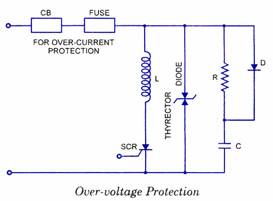
External voltage surges cannot be controlled by the SCR circuit designer. Voltage surges often lead to either malfunctioning of the circuit by unintentional turn-on of SCR or permanent damage to the device due to reverse breakdown. SCR can be protected against voltage surges by employingshunt connected non-linear resistance devices.
Such protective devices register a fall in resistance with the increase in voltage and so develop a virtual short-circuit across the SCR when a high voltage is applied. An over-voltage protection circuit employing thyrector-diode, which has low resistance at high voltage and vice-versa, is shown in figure.
Inductor L and capacitor C provides protection to SCR against large dV/dt and dI/dt. 🔗 External reference
Related Circuits
This application note explains how the transfer function of most operational amplifier circuits can be derived through a straightforward process of nodal analysis. The transfer function of operational amplifier (op amp) circuits is a critical aspect for understanding their behavior...
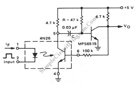
This is a pulse stretcher circuit utilizing an optocoupler. The circuit employs a 4N26 optocoupler in conjunction with a standard one-shot circuitry. The pulse stretcher circuit is designed to elongate the duration of an incoming pulse signal, which is particularly...
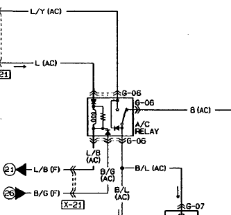
An automotive relay is being analyzed, which exhibits a more complex wiring configuration than typical relays. The diagram indicates that the B/G line maintains a high signal if certain conditions are met, specifically when the engine temperature is excessively...
The Wien-Bridge oscillator meets specific requirements due to the presence of a low-pass filter, a high-pass filter, and a 180-degree phase shift from the feedback networks connecting the input to the output. This configuration results in a total phase...

A center-tap 50Hz step-down transformer with two diodes is utilized to generate a series of positive sine pulses at 100Hz, which is applied to the base of Q6 through resistor R51. The 2N2646 is a unijunction transistor (UJT) housed...
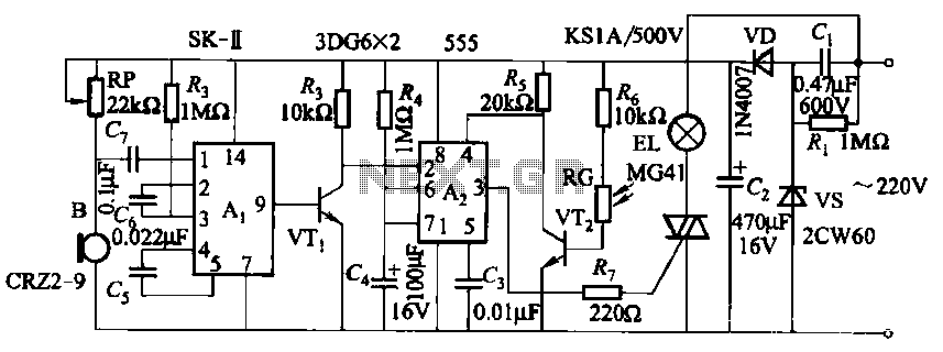
This circuit utilizes a dedicated voice integrated circuit (AI) of the SK type, which incorporates an internal bistable multivibrator and three inverting amplifiers. The 555 integrated circuit (IC) A2 is employed for delay control. The described circuit is designed to...
Warning: include(partials/cookie-banner.php): Failed to open stream: Permission denied in /var/www/html/nextgr/view-circuit.php on line 713
Warning: include(): Failed opening 'partials/cookie-banner.php' for inclusion (include_path='.:/usr/share/php') in /var/www/html/nextgr/view-circuit.php on line 713