
Low Power 12V Transformerless Power Supply

This circuit design allows for efficient power conversion from mains voltage to a usable DC output by employing a series capacitor and Zener diodes for rectification. The series capacitor (C1) is critical in limiting the current drawn from the AC mains, and its value can be adjusted according to the desired output current. The Zener diodes (D2 and D3) play a dual role; they rectify the AC input while also providing voltage regulation when the output exceeds a certain threshold. This arrangement allows for a more compact design compared to traditional bridge rectifiers, as it reduces the number of components required.
The rectification process occurs in two stages, where each half cycle of the AC waveform is utilized effectively. During the positive half cycle, current flows through D1, powering the load, and returning through D4. Conversely, during the negative half cycle, D3 and D2 allow current to flow in the opposite direction, again powering the load. This method ensures that both halves of the AC waveform contribute to the output, enhancing the overall efficiency of the circuit.
The output voltage is determined by the characteristics of the selected Zener diodes, allowing for flexibility in design. It is essential that capacitor C2 is rated for a voltage higher than the maximum expected output to prevent breakdown. The current available from this circuit is contingent upon the capacitance of C1; with a specified value of 220nF, the circuit can deliver around 15mA, which is suitable for low-power applications such as powering small relays or LED indicators.
Safety is paramount when working with mains-connected circuits. The design must incorporate adequate insulation and housing to prevent accidental contact with high voltage. It is advisable to use components rated for the voltages involved and to follow all relevant safety standards and regulations when implementing such a circuit. Proper enclosure will not only protect users but also ensure the longevity and reliability of the circuit's operation.Many circuits can be powered directly from the mains with the aid of a series capacitor (C1). The disadvantage of this approach is that usually only one half cycle of the mains wave-form can be used to produce a DC voltage. An obvious solution is to use a bridge rectifier to perform full-wave rectification, which increases the amount of current th
at can be supplied and allows the filter capacitor to be smaller. The accompanying circuit in fact does this, but in a clever manner that uses fewer components. Here we take advantage of the fact that a Zener diode is also a normal diode that conducts current in the forward direction. During one half wave, the current‚ows via D1 through the load and back via D4, while during the other half wave it‚ows via D3 and D2.
Bear in mind that with this circuit (and with the bridge rectifier version), the zero voltage reference of the DC voltage is not directly connected to the neutral line of the 230-V circuit. This means that it is usually not possible to use this sort of supply to drive a triac, which normally needs such a connection.
However, circuits that employ relays can benefit from full-wave rectification. The value of the supply voltage depends on the specifications of the Zener diodes that are used, which can be freely chosen. C2 must be able to handle at least this voltage. The amount of current that can be delivered depends on the capacitance of C1. With the given value of 220nF, the current is approximately 15mA. A final warning: this sort of circuit is directly connected to mains voltage, which can be lethal. You must never come in contact with this circuit! It is essential to house this circuit safely in a suitable enclosure. 🔗 External reference
Related Circuits
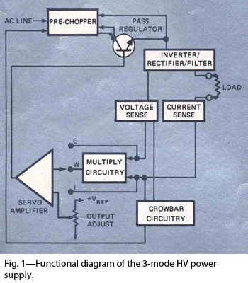
By combining switching and series-pass techniques, the designer of this high-voltage supply achieved 0.01% regulation at power levels up to 100W. The high-voltage power supply employs a hybrid approach that integrates both switching and series-pass regulation methods to achieve exceptional...
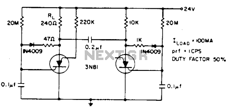
Electrolytic capacitors are not required to generate a 1 cps frequency. When the silicon-controlled switch (SCS) is triggered, the 0.2 µF commutating capacitor deactivates the other capacitor and charges its gate capacitor to a negative potential. The gate capacitor...
The LM1875 is a monolithic audio amplifier that provides very low distortion and high-quality performance for audio amplifier projects. The LM1875 delivers 20 watts into loads of 4 Ohms or 8 Ohms. The LM1875 audio amplifier is designed for applications...
These photos were made in the years 1956 and 1957. On photo nr. 3, on the right, at the bottom, is the GMD. The work that was done at the objekt was of course top secret. It was strictly...
This document presents a schematic diagram of an electret microphone pre-amplifier utilizing the LMV721 operational amplifier. The LMV721 is chosen for its low noise and low power characteristics. The electret microphone pre-amplifier circuit is designed to amplify the weak audio...
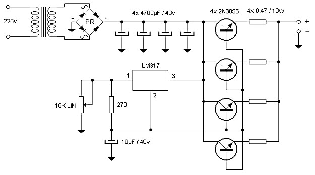
The wiring diagram illustrates that the source delivers a comparable amount of current through the parallel operation of four power transistors, which must be mounted on an effective heatsink. Voltage adjustment is achieved using an integrated LM317, which also...