
Low frequency oscillator-flasher

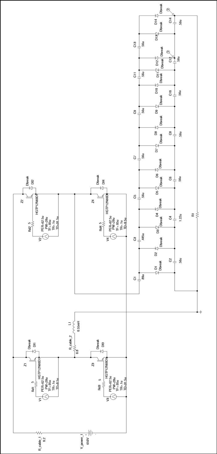
The circuit described operates effectively without the need for electrolytic capacitors, which are typically used in timing and filtering applications. The use of a 0.2 µF commutating capacitor plays a critical role in the switching mechanism of the SCS. Upon triggering, this capacitor discharges, causing the SCS to turn off the other capacitor in the circuit, which is essential for maintaining the desired operation of the system.
The gate capacitor, which is charged to a negative potential, is pivotal for controlling the SCS. The charging process occurs through a resistor, allowing the gate capacitor to reach a voltage of 24 volts. This voltage level is crucial as it retriggers the SCS, ensuring that the circuit continues to operate as intended.
The efficiency of 88% in delivering battery power to the load indicates a well-designed circuit that minimizes energy losses. This efficiency can be attributed to the careful selection of components and the design of the switching mechanism.
Furthermore, the ability to vary the resistors within the circuit provides flexibility in adjusting the pulse repetition frequency (PRF) and the duty cycle. This feature allows for customization based on the application's requirements, enabling the circuit to adapt to different operational conditions. By changing the resistance values, the timing characteristics of the circuit can be modified, which is crucial for applications requiring precise control over frequency and duty factor.
Overall, this circuit design demonstrates a robust approach to managing power delivery and timing without the need for traditional electrolytic capacitors, thus enhancing reliability and performance.Electrolytic capacitors are unnecessary to generate a 1 cps frequency. As an scs triggers on, the 0.2 µ¥ commutating capacitor turns off the other one and charges its gate capacitor to a negative potential. The gate capacitor charges towards 24 volts through 20 retriggering its scs. Battery power is delivered to the load with 88% efficiency. The 20 resistors can be varied to change prf or duty factor.
Related Circuits
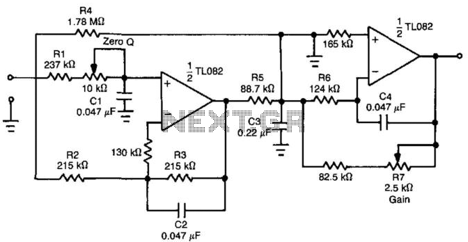
By introducing an additional transmission zero to the stopband of a low-pass filter, a sharper roll-off characteristic can be achieved. The filter design example illustrated in Figure 30-1(a) demonstrates that the time-domain performance of the low-pass section can also...
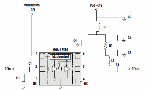
This application note discusses the use of Avago Technologies' MGA-675T6 for 5-6 GHz applications. The MGA-675T6 is internally integrated with shutdown and biasing circuitry, which simplifies the external circuitry. The shutdown feature allows the low noise amplifier (LNA) to...
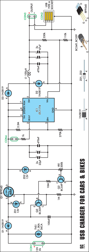
A regular charger was tested and found to consume 13mA with no load. It features an integrated power LED, which significantly contributes to standby current consumption. However, since the cigarette lighter socket is powered only when the engine is...
A voltage-to-frequency converter can be constructed using the LM231/331 chip, making it a cost-effective solution for applications such as analog-to-digital conversion and frequency-to-voltage conversion over extended periods. The LM231/331 series of voltage comparators can be effectively utilized to design a...
Thesis by Rafael Bräg at the University of Canterbury, New Zealand, in cooperation with the Universität Karlsruhe, Institut Elektrotechnik und Hochspannungstechnik. The thesis presents a comprehensive study conducted by Rafael Bräg, focusing on advancements in the field of electrical engineering....
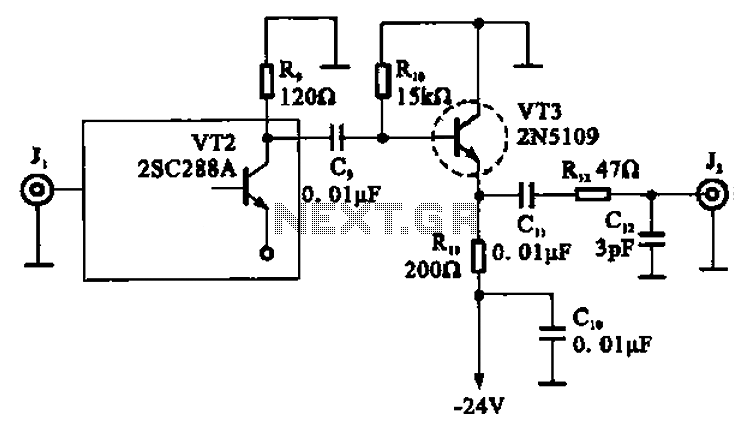
A high-frequency signal is displayed in the output amplifier. The circuit consists of a VI3 common collector amplifier (emitter follower) designed to enhance the child-band. It is a high-frequency amplifier (1-250 MHz) that increases the output voltage and boosts...