
Low resistance continuity tester
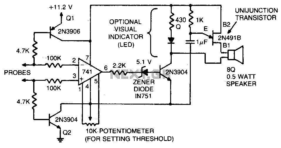
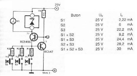
The tester operates by utilizing a combination of resistors, transistors, and an operational amplifier to ensure accurate testing of IC printed circuit boards. The two 4 kΩ resistors are strategically placed to limit the current flow, thereby protecting the operational amplifier from potential damage due to excessive current. The transistors serve as switches that control the flow of current, ensuring that the operational amplifier is only activated when the probe circuit is completed. This design feature enhances the reliability of the tester by preventing false readings that may occur if the circuit is incomplete.
The inclusion of the zener diode in the circuit adds an additional layer of protection and functionality. By being in series with the output of the operational amplifier, the zener diode regulates the voltage levels, ensuring that the audio oscillator remains inactive until the operational amplifier's output is sufficiently amplified. This prevents premature activation of the audio oscillator, which could lead to erroneous test results.
Overall, this tester is an essential tool for verifying the functionality of IC printed circuit boards, providing a reliable means of ensuring that circuits are properly completed and operational before further testing or implementation. The careful selection of components and their arrangement within the circuit ensures that the tester operates efficiently and accurately, making it a valuable asset in electronic testing and diagnostics.This tester can be used to check IC printed circuit boards. Two 4 K resistors and the transistors connected to them prevent current flow through the operational amplifier until the probe circuit is completed The zener diode in series with the operational amplifier output prevents audio oscillator operation until the positive output of the operational amplifier has sufficient amplitude. 🔗 External reference
Related Circuits
The micropower circuit automatically provides shutdown, power-up, and low-battery lockout functions without requiring software or operator control. The micropower circuit is designed to manage power efficiently in battery-operated devices, ensuring optimal functionality while conserving energy. The shutdown feature is activated...
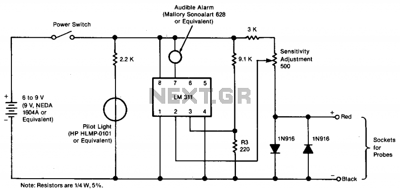
The tester provides an audible indication, eliminating the need for the user to directly observe a meter reading. Additionally, the current and voltage output of the tester are strictly limited, with a maximum of 0.6 volts DC and 3...
This document presents a very low-power monolithic 1.9GHz silicon Low Noise Amplifier (LNA) that operates with a total current consumption of 1.75mA, which includes the bias circuit. The described Low Noise Amplifier (LNA) operates at a frequency of 1.9GHz, making...
The electronic scheme provided can be used to design a Zener diode tester utilizing a few electronic components. This Zener tester, in conjunction with a multimeter, allows for the precise measurement of the threshold voltage of a Zener diode....
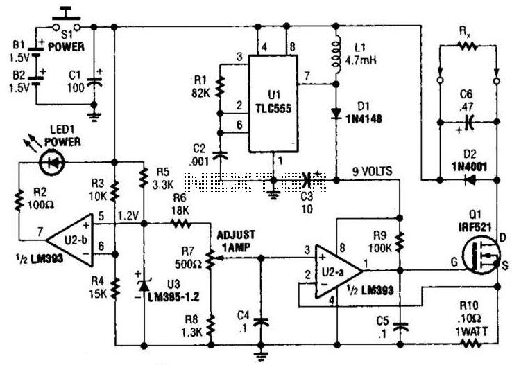
Useful for low-resistance measurements, this 1-A current source will produce 1 A in unknown resistance Rx. For best results, Rc should be less than 1 to 2, because only 3 V are available. Ul is a flyback converter to...
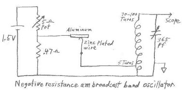
This circuit can be easily powered from a 1.5 volt battery. One characteristic of N type negative resistance devices is that they typically require a very low bias source resistance in order to keep the bias voltage stable within...