
Current Source For Resistance Measurements Circuit

The described circuit comprises a 1-A current source designed specifically for low-resistance measurements, where the primary objective is to accurately determine the resistance of an unknown resistor, Rx. The current source is capable of sourcing a constant current of 1 A, which is essential for obtaining precise resistance values. The implementation requires that the resistor Rc, which is part of the current source configuration, be selected with a value of less than 1 to 2 ohms. This specification is critical due to the limited supply voltage of 3 V available for the circuit operation, which can restrict the maximum achievable current and affect measurement accuracy.
The circuit utilizes a flyback converter, denoted as Ul, which is responsible for stepping up the voltage to 9 V for another component in the circuit, U2. Flyback converters are efficient power supply circuits that can provide isolated output voltages, making them suitable for applications where higher voltage levels are required from a lower input voltage. The 9 V output from the flyback converter can be utilized to power additional components or circuits that require higher voltage levels, ensuring that the overall system can function effectively.
In summary, the current source circuit is designed for low-resistance measurement applications, operating at a constant current of 1 A, with specific attention given to the resistor values to optimize performance under the constraints of a 3 V supply. The integration of a flyback converter enhances the circuit's versatility by providing necessary higher voltage levels for additional components. Useful for low-resistance measurements, this 1-A current source will produce 1 A in unknown resistance Rx. For best results, R,c should be less than 1 to 2, because only 3 V are available. Ul is a flyback converter to generate 9 V for U2. 🔗 External reference
Related Circuits
This circuit serves as a dependable alternative to thermally-activated switches designed for flashing Christmas tree lamps. The arrangement consisting of Q1, Q2, and associated resistors activates the silicon-controlled rectifier (SCR). The timing function is determined by resistors R1, R2,...
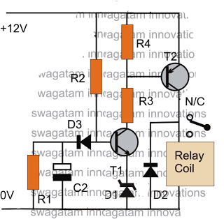
The post discusses a simple delay ON circuit that enables a connected load at the output to be activated with a predetermined delay after the power switch is turned ON. This circuit can be utilized in various applications that...
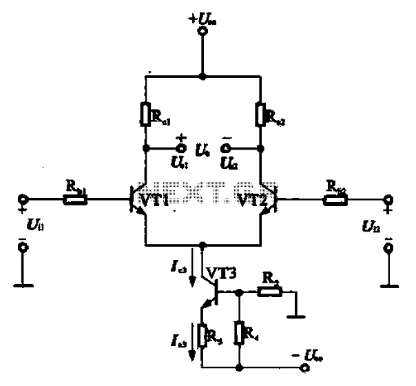
A constant current source is utilized in the differential amplifier circuit, which includes an emitter resistor. In this configuration, an increase in the output voltage (Ua) is not desirable. To ensure that Ua remains stable, the supply voltage (Ucc)...
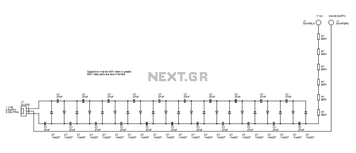
A basic mains driven Cockroft ladder high voltage generator is shown in the schematic. This is functionally the same as a project in Electronics Today International many years ago. The peak mains voltage of 340V appears across each capacitor...
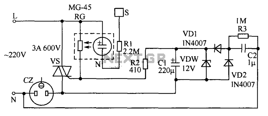
The circuit operates by detecting a finger touch on a metal sheet (S), which activates a neon tube light (N). The combination of the neon tube and a photoresistor (RG) acts as an optocoupler, reducing the resistance of RG....
Infrared remote controls are using a 32-56 kHz modulated square wave for communication. These circuits are used to transmit a 1-4 kHz digital signal (OOK modulation) through infra light (this is the maximum attainable speed, 1000-4000 bits per sec)....