
Negative Resistance Oscillator with Tunnel Diode
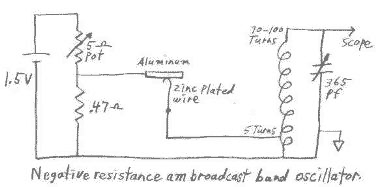
The circuit described operates as a negative resistance oscillator, utilizing a homemade N-type negative resistance device. The circuit is powered by a 1.5-volt battery, which is suitable for low-power applications. The key component, the negative resistance device, exhibits a narrow negative resistance region that necessitates a very low bias source resistance, ideally around 1 ohm or less. This low resistance is crucial for maintaining stability in the negative resistance operation, as higher resistance can lead to instability and abrupt voltage changes.
The biasing arrangement includes a 0.47-ohm resistor in series with a 5-ohm potentiometer, which allows for fine-tuning of the bias voltage. The circuit draws a significant amount of current (500 to 600 mA) to achieve the necessary operating conditions for the negative resistance device. It is noted that while a single AA cell can power the circuit, a D cell is recommended for better performance under these current demands.
The circuit may also utilize an LC oscillator or a relaxation oscillator configuration, with adjustments made using a curve tracer or an oscilloscope to monitor the oscillation characteristics. The potential for switching between a curve tracer and the oscillator circuit using a DPDT switch adds versatility to the testing and adjustment process. Furthermore, the option to introduce a 12-volt AC signal from a transformer allows for additional biasing control, facilitating the observation of RF bursts on an oscilloscope.
Overall, this circuit exemplifies a creative approach to utilizing negative resistance devices in oscillator applications, demonstrating the importance of careful biasing and adjustment to achieve stable oscillation characteristics.This circuit can be easily powered from a 1.5 volt battery. One characteristic of N type negative resistance devices is that they typically require a very low bias source resistance in order to keep the bias voltage stable within the negative resistance region. With too high of bias resistance, the voltage, as it enters the negative resistance region, will have a tendacy to suddenly jump past it.
This is why a gap is seen in the curve (see photo). This homemade device, with its narrow negative resistance region, requires an even lower bias source resistance than a typical tunnel diode. A typical tunnel diode can be biased within the negative resistance region with a bias resistance of around 20 ohms.
This device works best when the bias resistance is 1 ohm or less.
This device, like many others that I have been making, has a symmetrical curve in both the positive and negative direction and can work with the battery connected either way. Just for the sake of being consistant, I did most experimenting with the aluminum biased positive with respect to the zinc covered wire.
The low (approx 250 millivolt) bias voltage for this device was produced across a .47 ohm resistor, connected to the battery through a 5 ohm pot. This means drawing 500 to 600 milliamps from a 1 1/2 volt battery in order to supply approx 35 ma to the device.
A 5 ohm pot is not as common as a 50 k ohm pot but can be easily obtained at a surplus outlet. It might also be easy to improvise a 5 ohm pot from something like a pencil lead. It was easy to run the circuit from a single AA cell but of course a D cell is much more suitable when drawing this much current. An emitter follower circuit could be a much more efficient way to bias this device but I like to have this circuit completely void of any commercially made transistors or other active devices.
I wanted to be absolutely sure, that this homemade device is indeed what is actually producing the oscillations. Below are schematics and waveform pictures of an LC oscillator and a relaxation oscillator. Adjustment of these circuits can be tricky but easily done if things are set up rite. I have had very little success in getting the circuit to oscillate while trying to adjust just the catwhisker with a set bias voltage.
The easiest and best way to adjust this circuit is to switch the device out of the circuit and to a curve tracer. Adjust the catwhisker until you observe a negative resistance region, similar to that shown in the picture above, and then switch the device back into the oscillator circuit.
The bias pot is then adjusted, looking at an oscilloscope, for a clean oscillation signal. The circuit above, for the sake of reducing clutter, does not show a dpdt switch that I sometimes use to switch the negative resistance device between a curve tracer and the oscillator circuit. A curve tracer is not always a handy thing to have around. The circuit can also be easily adjusted by using just an oscilloscope and a 12 volt transformer, as shown in the partial diagram below.
While the normal dc bias is applied and adjusted to approx 200 to 250 millivolts across the .47 ohm resistor, 12 volts ac from a transformer can be switched into the circuit through a 100 to 200 ohm resistor. This applies a varying dc bias to the negative resistance device. The catwhisker can then be adjusted until you see 60 cycle bursts of rf on the scope. If the ac voltage is now switched off, a continuous oscillation can usually be achieved by watching the oscilloscope and adjusting the bias pot.
The circuit will then be running entirely from the 1-1/2 volt battery. The audio frequency oscillator can be easily adjusted without an oscilloscope or curve tracer by simply connecting a pair of headphones across the inductor. The temporary application of the 12 volts is still helpful.
Related Circuits
An oscillator, a small power stage, some modulation, and a tiny loop antenna make RF for experiments on at 187.5 kHz on the United States' FCC Part 15 Lowfer band (1600-1750 meters). This is a low power signal source...

A Crystal Colpitts oscillator can be constructed using a parallel mode crystal and a transistor. The circuit is depicted in the accompanying figure. In this configuration, an inductance is utilized. The Crystal Colpitts oscillator is a type of electronic oscillator...

The following diagram illustrates the schematic of a simple, easily tuned adjustable sine and square wave oscillator. This circuit generates sine and square wave signals at frequencies ranging from below 20 Hz to above 20 kHz. The advantage of...
Below are a couple circuits you can use to produce a 32.768 KHz square wave from a common watch crystal. The output can be fed to a 15 stage binary counter to obtain a 1 second square wave. The...
A simple variable frequency oscillator utilizing a 555 timer IC to generate a square wave frequency that can be adjusted using a potentiometer. The circuit operates primarily on the principles of astable multivibrator configuration using the 555 timer IC, which...
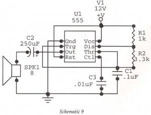
This circuit features an astable oscillator constructed around a 555 timer, generating an alarm tone of 1.8 kHz, which directly drives a speaker. It serves as a fundamental alarm circuit that can be utilized in various projects. Although the...
Warning: include(partials/cookie-banner.php): Failed to open stream: Permission denied in /var/www/html/nextgr/view-circuit.php on line 713
Warning: include(): Failed opening 'partials/cookie-banner.php' for inclusion (include_path='.:/usr/share/php') in /var/www/html/nextgr/view-circuit.php on line 713