
cruddy v 2 line follower mobile robot
The Cruddy version 2 robot operates as a line-following device, employing a series of digital logic gates to process input signals from sensors that detect the line on the ground. The design typically includes two main components: the sensor array and the logic circuit.
The sensor array is composed of infrared (IR) sensors that continuously monitor the surface beneath the robot. When the sensors detect a change in reflectivity—indicating the presence of a line—the output signal is directed to the digital logic gates. The gates are configured to interpret these signals and control the motors that drive the robot's wheels.
The logic circuit may consist of various gates such as AND, OR, and NOT gates, which work together to create a control logic that determines the movement of the robot. For example, if the left sensor detects the line, the logic circuit can be designed to stop the left motor while allowing the right motor to continue, thus steering the robot back onto the line.
The absence of a microcontroller simplifies the design and reduces costs, making it an excellent educational project for understanding the fundamentals of digital electronics and robotics. Furthermore, the aesthetic enhancements contribute to the robot's appeal, showcasing how functional design can merge with visual creativity in electronic projects.
Overall, the Cruddy version 2 robot exemplifies a practical application of digital logic in robotics, illustrating the principles of sensor integration and motor control without the complexity of programmable components.This is my 5th robot. He is Cruddy version 2. Still he is a line following robot but has now abetter circuit design (originally designed by me) and has cool appearance :D This project doesn`t have any microcontroller. It is designed through digital logic gates only. I used two.. 🔗 External reference
Related Circuits
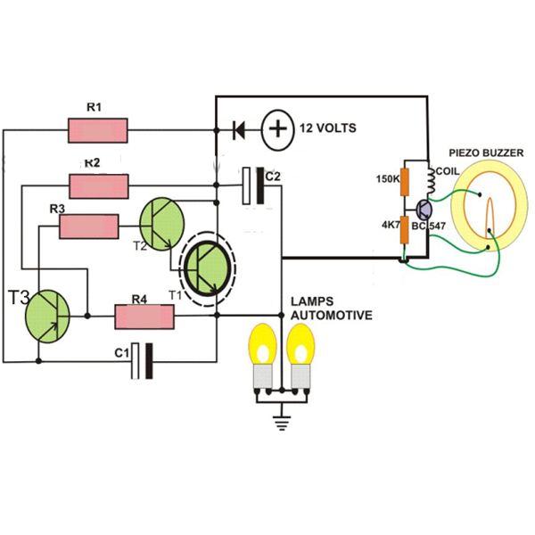
This circuit is designed to create a flasher unit for a motorbike. It is a simple turn signal flasher circuit that can be easily built and installed in any two-wheeler for the desired functionality. The circuit uses only two...

The circuit is designed to seek light, enabling it to follow a flashlight in a darkened environment. Two photocells are utilized to determine the direction of movement for the robot. Each photocell connects to an operational amplifier (op-amp) configured...

Utilizing a single current source for both the charge and discharge paths in this circuit guarantees that the rise and fall times at the capacitor terminal are identical. A Darlington pair is employed to ensure consistent biasing of the...
After completing the robot for the competition, updates to the blog were paused due to disappointment over not finishing the robot on time. An update on the progress made thus far is being provided. The motor driver was changed...
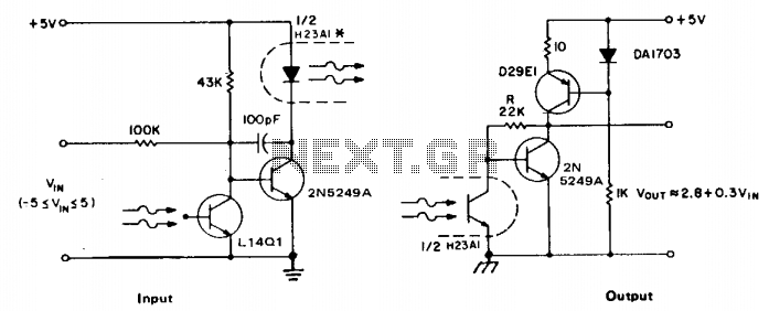
The accuracy of direct linear coupling of analog current signals through an optocoupler is influenced by the linearity of the coupler and its temperature coefficient. Implementing an additional coupler for feedback can enhance linearity, but only if both couplers...

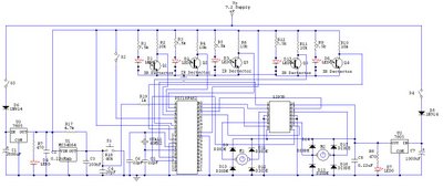
The schematic for controlling the motors is divided into three main sections, each serving a distinct function. The primary components featured in the schematic include the PIC 18F252 microcontroller, the SN754410 motor driver, and 2N2222 transistors. At the top...
Warning: include(partials/cookie-banner.php): Failed to open stream: Permission denied in /var/www/html/nextgr/view-circuit.php on line 713
Warning: include(): Failed opening 'partials/cookie-banner.php' for inclusion (include_path='.:/usr/share/php') in /var/www/html/nextgr/view-circuit.php on line 713