
Low Voltage to 30 kV Out

The circuit employs a flyback transformer sourced from older televisions or monitors. The input voltage is connected to a transistor (Q1), typically a 2N3055, configured in a switching arrangement to drive the transformer. The circuit includes a high voltage (HV) diode for rectification, essential for converting the AC output from the transformer into a usable high voltage DC. The secondary winding of the flyback transformer is responsible for generating the high voltage output.
In terms of components, resistors R1 and R2 are used to limit the current flowing through the transistors and to stabilize the operation of the circuit. The design may require a heat sink to manage the thermal load on the transistors, especially when utilizing larger flyback transformers or higher input voltages. For improved performance and reliability, it is advisable to use transistors with higher power ratings, particularly in applications involving sustained operation.
For modifications, an inductor (L1) can be added to the circuit to reduce stress on the transistors and the power supply by limiting current during the switching transitions. This modification has been utilized successfully in similar inverter designs.
When selecting a flyback transformer, it is crucial to ensure that the high voltage secondary winding is intact and that the primary winding is in good condition. If the primary winding has failed, it may be removed without damaging the secondary winding. It is important to identify the return path for the high voltage winding, which may be indicated by a different color wire or a separate exit point from the transformer. Testing for continuity with an ohmmeter may not be effective if the transformer has an integrated high voltage rectifier, as the forward voltage drop will exceed the multimeter's battery voltage. A winding showing infinite resistance to all other terminals is likely the high voltage return.
Overall, this circuit allows for the generation of high voltage from a low voltage source, suitable for various applications, including high voltage experiments and gas discharge excitation. Proper precautions and component selections are necessary for safe and effective operation.The basic circuit described in this document is capable of generating up to 30 kilovolts or more from a low voltage DC source using the flyback (LOPT) transformer salvaged from a B/W or color TV or computer monitor. Typical output with a 12 VDC 2 A power supply or battery will be 12, 000 V. Maximum output current at full voltage is typically around 1 to 2 mA. Higher currents are available but the output voltage will drop. At 2 kV, more than 10 mA may be possible depending on your particular flyback transformer input voltage and current. Before thinking about experimenting with anything using or producing high voltages, see the document: Safety Guidelines for High Voltage and/or Line Powered Equipment.
While the circuit described below isn`t likely to be lethal using the suggested input voltage and components, who knows how you might `enhance` it! :-) +Vcc Q1 +-+ o | ):: | B |/ C ):: | +-| 2N3055 ):: | | | E 5 T ):: +-|>|-o +HV | | | )::( HV Diode, usually | | -_- )::( built in.
| | )::( +-|-+ ::( | | Q2 _-_ )::( | | | )::( Secondary (HV) winding, | | B |/ E 5 T )::( intact. | | -| 2N3055 )::( | | | | C )::( | | | | )::( | | | +-+ ::( | | | ::( | | -+ :: +-o -HV | | 2 T ):: | | +-+ :: | | | 2 T ):: T1 - Flyback transformer from B/W or | +-+ color TV or computer monitor. | | | R1 | R2 +-///-+-///-+ 110 27 _|_ 5 W 5 W - TO3Pn TO220 _ _ / | o | | O | View from front (label side).
|-| |-| |Label| | | B = Base, E = Emitter, C = Collector. |_| | Label | | | | |_| If there is an exposed metal tab, that is | | | | | | the Collector as well. B C E | | | B C E A slightly modified version of this basic circuit which I use as an RF source to excite a glow discharge in helium-neon laser and other gas discharge tubes is shown in: Flyback Based RF Source. This one uses a flyback transformer without a high voltage rectifier (or with the rectifier removed).
The inductor, L1, is an addition that should reduce the stress on the transistors and power supply by limiting current at the time each of the transistors go into saturation just before the base drive switches to the opposite side. I have not specifically tested this circuit with the inductor but have used it with similar inverters.
These designs are similar to circuits found in: "Build your own working Fiberoptic, Infrared, and Laser Space-Age Projects", Robert E. Iannini, TAB books, 1987, ISBN 0-8306-2724-3 and many other places. For larger (e. g. , color TV or monitor) flybacks, or use with more than 12 VDC in, transistors with higher power ratings may be needed for sustained operation in addition to a good heat sink.
An alternative is to parallel more than one power transistor along with small (e. g. , . 05 ohm, 2 W) current balancing resistors in series with their emitters. Read the following in its entirety! This assumes the basic circuit using a small flyback and input voltage of 12 VDC or less. Some modifications may be needed when using larger flybacks and higher input voltages. Obtain flyback transformer with known good HV secondary winding. primary may be left intact if it is known to be in good condition - non shorted. A flyback removed due to failure may be used if it was the primary that failed and the primary turns can be removed without damaging the HV secondary or losing the secondary return connection! Flybacks fail in both ways (primary and secondary). Locate the return for the high voltage winding. This may be a different color wire than the low voltage winding or may exit from the potted part of the flyback in a different place.
It is not possible to use an ohmmeter to locate the return for the high voltage winding if your flyback has a built-in HV rectifier or multiplier as the forward voltage drop of the rectifier diodes is much greater than the battery voltage used in your multimeter. However, a winding connection that has infinite resistance to every other terminal is likely to be the HV return
🔗 External reference
Related Circuits
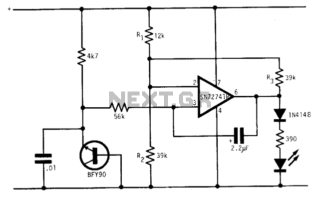
Under optimal battery conditions, the LED remains off. As the battery voltage decreases, the LED starts to flash, and when the battery reaches a low voltage condition, the LED illuminates continuously. This circuit is designed for use with a...

There are many applications where the accuracy of a digital or analog (bar graph) output is not necessary, but a solution that offers more than a simple low/high indicator is desirable. In various electronic applications, there exists a need for...
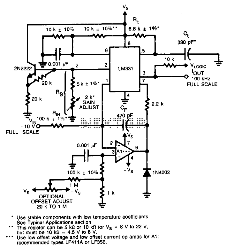
This circuit utilizes a conventional operational amplifier in conjunction with a feedback capacitor (CF) to perform integration. When the output of the integrator exceeds the nominal threshold level at pin 6 of the LM131, it triggers the timing cycle....
This circuit is designed to drive a low-power speaker using a sound effects module or a noise generator. It can also be utilized to create amplified speakers for computer use. The circuit amplifies the input signal by a factor...
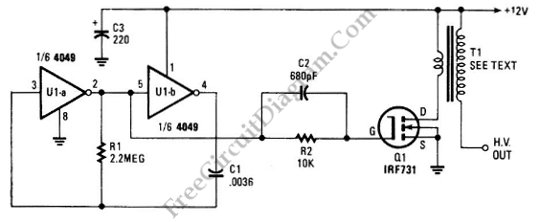
The schematic diagram below illustrates a circuit for a high voltage generator. This circuit employs a 4049 hex inverter as an oscillator, and it can be utilized for ignition purposes. The high voltage generator circuit is designed to convert a...
This circuit is constructed using two LT1001 operational amplifiers (OP-AMPs), with the output of the OP-AMP saturating at +5V. The power supplies used are +5V and ground. According to the documentation, applying +1V to the "Servo Input" results in...