
British Police Car SirenCircuit With 555 Timer IC
The sound generator circuit designed to simulate a British police car siren utilizes two 555 timer integrated circuits (ICs) configured in astable mode. The first 555 timer generates a square wave signal, which produces a frequency that mimics the characteristic oscillation of a police siren. The frequency can be adjusted by varying the resistor and capacitor values connected to the timer, allowing for fine-tuning of the sound output.
The output from the first 555 timer is fed into the second 555 timer, which acts as a modulator. This second timer alters the duty cycle of the square wave, creating a variation in the tone that further simulates the dynamic nature of a real siren. The modulation can be achieved by using a potentiometer in the circuit, which allows for real-time adjustments to the sound characteristics.
The circuit requires a power supply, typically in the range of 5V to 15V, depending on the specifications of the 555 timers used. A small speaker or piezo buzzer is connected to the output of the second timer, where the generated sound is emitted. The overall design is compact and can be easily assembled on a breadboard or a printed circuit board (PCB).
Additional components that may be included in the circuit are bypass capacitors to stabilize the power supply and ensure consistent operation of the timers. A diode may also be added to protect the circuit from potential back EMF generated by the speaker. This sound generator circuit serves as an excellent educational project for understanding timer IC applications and sound synthesis.This circuit displaying the sound generator which will simulate British police car siren. The circuit is built using 2 pieces of timer IC 555 to .. 🔗 External reference
Related Circuits
Car and Motorcycle Battery Tester Circuit. Going camping today often requires bringing various electronic devices for daily activities or entertainment. Typically, a charged lead-acid battery and a power source are essential. The Car and Motorcycle Battery Tester Circuit is designed...
A very long time constant is provided by R1 and C1. C1 discharges, and the near-zero voltage at its positive lead is applied to the high-impedance inputs of the circuit. In this circuit, the combination of resistor R1 and capacitor...
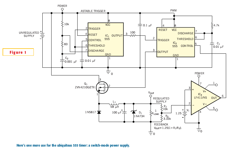
Most switch-mode power supplies utilize a PWM (pulse-width-modulated) output that is regulated through voltage feedback. A 555-timer IC can be used to generate PWM at a low cost. The circuit diagram illustrates how to convert a 555 PWM circuit...
The frequency formula of a 555 oscillator is well-known. For given resistors and capacitors, the frequency can be calculated using a specific formula derived from mathematical principles. The 555 timer IC is widely used in various applications, including oscillators, timers,...
The 555 timer is a highly versatile integrated circuit that has found applications in a wide range of devices, from toys to spacecraft. This chip can function as an oscillator, a Schmitt trigger, and more. The 555 timer is a...
This FM radio-controlled anti-theft system can be used with any device operating on a 6 to 12-volt DC power supply. The mini VHF FM transmitter is installed in the vehicle at night when it is parked in the driveway...
Warning: include(partials/cookie-banner.php): Failed to open stream: Permission denied in /var/www/html/nextgr/view-circuit.php on line 713
Warning: include(): Failed opening 'partials/cookie-banner.php' for inclusion (include_path='.:/usr/share/php') in /var/www/html/nextgr/view-circuit.php on line 713