
Remote Control Tester Circuit using Infra red sensor IC TSOP 1738

The remote control tester circuit utilizes the TSOP1738 infrared sensor, which is designed to receive modulated infrared signals from remote controls. The circuit operates by connecting the TSOP1738 to a power supply, typically 5V, and interfacing it with an LED indicator.
When the infrared sensor detects a signal from a remote control, it outputs a low logic level (0V) to the connected LED. This causes the LED to illuminate, effectively signaling that the remote control is operational. The circuit is straightforward, consisting of minimal components: the TSOP1738, an LED, a current-limiting resistor for the LED, and a power source.
The schematic diagram illustrates the connections between these components. The TSOP1738 has three pins: Vcc (power), GND (ground), and OUT (output). The Vcc pin is connected to the positive terminal of the power supply, while the GND pin is connected to the negative terminal. The OUT pin connects to the anode of the LED through a current-limiting resistor, with the cathode of the LED connected to ground.
This configuration ensures that the LED will light up only when the TSOP1738 detects an infrared signal, providing a simple yet effective means to test the functionality of various remote controls. The circuit can be assembled on a breadboard for prototyping or soldered onto a PCB for a more permanent solution.A simple remote control tester circuit with diagram and schematic using infra red sensor IC TSOP1738. An LED will blink when IR waves falls on it which indicates remote control functioning.. 🔗 External reference
Related Circuits
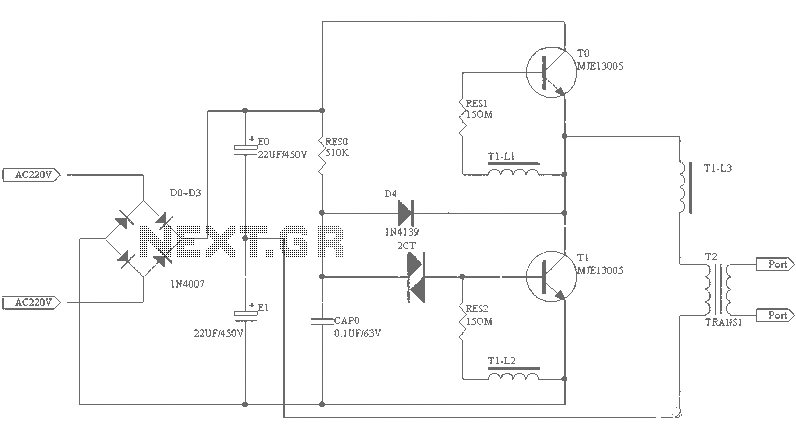
A small (2 to 3 meters) neon electronic transformer circuit diagram is provided below. The described circuit diagram is intended for use with neon lighting systems, specifically those requiring a transformer to operate efficiently within a range of 2 to...
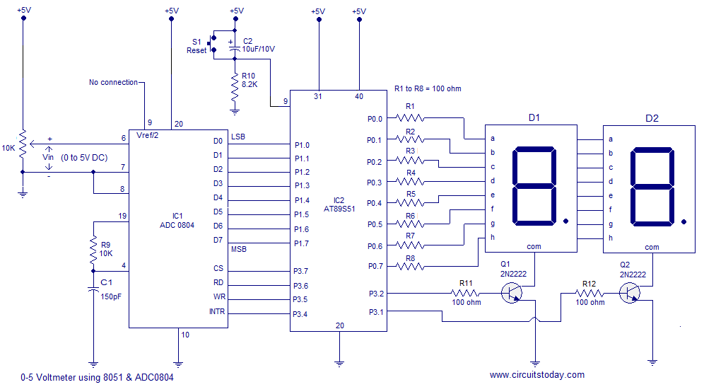
A simple 0-5 digital voltmeter utilizing the 8051 (AT89S51 microcontroller) is presented, accompanied by a circuit diagram and assembly language (ASM) code. This digital voltmeter is designed for straightforward voltage measurement. The circuit employs an AT89S51 microcontroller, which serves as...
The figure illustrates a schematic circuit of a UV sensor. When voltage is applied between the cathode and anode, and UV radiation passes through the quartz glass tube on the cathode's optical surface, the cathode material, which is coated...

This device features a small DC motor fan situated above a container filled with deodorant liquid or gel, powered by a D cell battery. A photocell is integrated to deactivate the fan in low light conditions. An LED indicator...
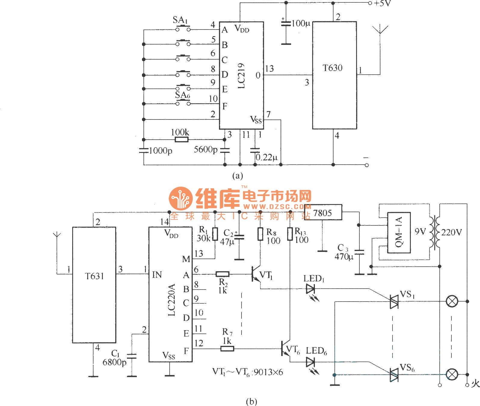
The circuit utilizes the long-wave wireless transceiver T630/T631 to manage a 6-channel load. It is characterized by low power consumption, high resistance to interference, and a simple structure. The circuit design incorporates the T630/T631 transceiver, which operates in the long-wave...
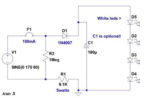
If the AC supply is 220 volts, which resistor should be replaced and with which one? Since 220V is twice that of 110V, the resistance value needs to be doubled accordingly. It is suggested to replace the 9.1kΩ resistor...