
Low voltage detector
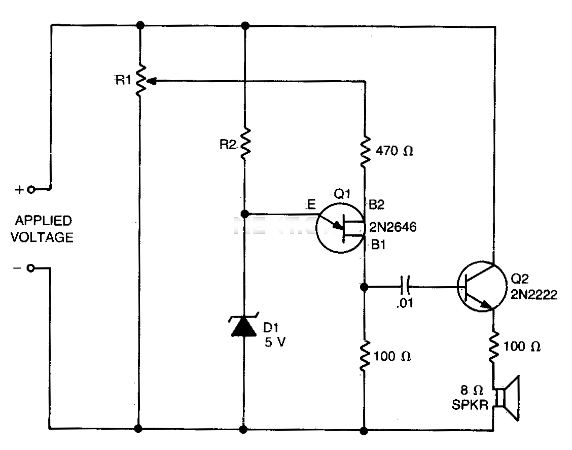
The circuit operates as a voltage monitoring system that utilizes a combination of resistors, a zener diode, and transistors to provide an alert when the voltage level of a battery drops below a predefined threshold. The configuration begins with a 12-volt battery supplying the circuit. Resistor R1, valued at 10 kΩ, acts as a voltage divider, setting the reference voltage for the detection mechanism. Resistor R2, at 5 kΩ, provides the necessary biasing for the zener diode D1, which regulates the voltage to approximately 5 volts. This zener diode may be replaced by a series of forward-biased silicon rectifiers that also yield a similar voltage drop.
Transistor Q1, a Unijunction Transistor, is pivotal in the detection process, triggering the alert mechanism when the voltage falls below the threshold established by R1. The second transistor, Q2, serves as a small-signal or switching NPN transistor, which amplifies the signal from Q1 to activate the speaker. The speaker generates beeps as a warning signal that corresponds to the level of undervoltage detected. The frequency of the beeping is directly proportional to the amount of voltage drop, providing a clear indication of the battery's status.
The circuit is designed to draw minimal current when the detector is connected, ensuring that it does not adversely affect the operation of other devices powered by the same battery. In scenarios where multiple voltages are monitored, it is recommended to set R1 to draw only 1 mA to 2 mA, maintaining efficiency while ensuring accurate voltage monitoring. The selection of the zener diode D1 to be around half of the desired trip voltage is critical, as it allows for optimal performance of the voltage detection circuit. Overall, this design effectively combines simplicity and functionality, making it suitable for various battery monitoring applications.The values of Rl, R2, and D1 are selected for the voltage applied. Using a 12-volt battery, Rl = 10 K, R2 = 5 K and D1 is a 5-volt zener diode, or a string of forward-biased silicon rectifiers equaling about 5 volts. Transistor Ql is a general-purpose UJT (Unijunction Transistor), and Q2 is any small-signal or switching NPN transistor.
When detector is connected across the battery terminals, it draws little current and does not interfere with other de vices powered by the battery If voltage drops below the trip voltage selected with the Rl setting, the speaker beeps a warning. The frequency of the beeps is determined by the amount of undervoltage. If other voltages are being monitored, select Rl so that it draws only 1 mA or 2 mA. Zener diode D1 is about one-half of the desired trip voltage, and R2 is selected to bias it about 1 mA. 🔗 External reference
Related Circuits

The PB1009K is a silicon monolithic integrated circuit (IC) designed for GPS receivers. This IC incorporates a complete voltage-controlled oscillator (VCO), a second intermediate frequency (IF) filter, a 4-bit analog-to-digital converter (ADC), and a digital control interface, all aimed...
A circuit is described that transmits temperature data over an IR link. This allows isolation of the temperature sensor. The circuit operates by utilizing an infrared (IR) transmitter and receiver pair to wirelessly transmit temperature readings from a sensor to...
This project is an extension of Metal Detector MkI, demonstrating the detection of metal objects. It is the second in a series of circuits that allows significant experimentation, particularly for those with a Cathode Ray Oscilloscope (CRO) and various...
This circuit utilizes an LM339 quad voltage comparator to create a time delay and manage a high current output at low voltage levels. Approximately 5 amps of current can be sourced using a pair of fresh alkaline D batteries....
Men particularly enjoy the convenience of television remote controls, often to the annoyance of their female partners. They tend to want to know what they are missing when the TV is tuned to a specific program, leading them to...
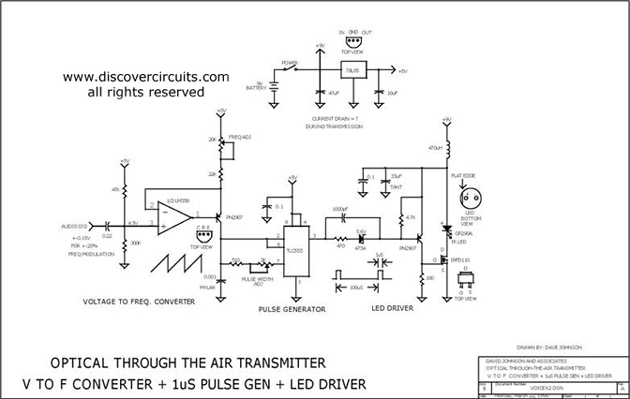
This circuit receives the signal from the amplifier and emits powerful 1μs infrared light pulses from a low-cost LED, which are frequency modulated by the audio information. The 10kHz center frequency of the pulse stream is sufficiently low, allowing...