
Metal Detector MkII
The metal detector circuit operates primarily on the principle of inductive coupling and amplitude modulation. The feedback oscillator generates a high-frequency oscillation that is influenced by the presence of metal objects within the detection coil's vicinity. The interaction between the magnetic field generated by the coil and the conductive properties of the metal leads to the formation of eddy currents, which effectively alter the inductance of the coil.
The circuit's design emphasizes modularity, allowing for easy experimentation with individual components. Each building block serves a distinct function, from signal generation to amplification and output. The feedback mechanism ensures stability in the oscillator's operation, while the capacitors are crucial for smoothing and timing aspects, which are vital for accurate detection and response.
In practical applications, the circuit can be fine-tuned by adjusting the potentiometer, allowing users to set sensitivity levels based on the types of metals they wish to detect. Additionally, integrating a CRO enables visual feedback, facilitating deeper understanding and adjustments in real-time as different objects are introduced into the detection field.
This project not only illustrates the fundamental principles of metal detection but also serves as a platform for further exploration and innovation in electronic circuit design.This project is an extension of Metal Detector MkI, and shows how metal objects are detected. It is the second in a series of circuits and allows a great deal of experimentation, especially if you have a CRO (Cathode Ray Oscilloscope) and a few items to detect. You can view the waveforms and see exactly how they alter as an object is brought into the field of the coil. Metal detectors will detect ferrous (iron, steel, stainless steel) as well as non-ferrous (copper, tin, gold, lead, silver, aluminium) as well as alloys (brass, cupro-nickel, pewter etc). Depending on the complexity of the circuit, a metal detector will be able to discriminate between a lump of gold and an aluminium ring-pull from a drink-can.
The circuit we have presented in this project is very simple and works on the principle of detecting the amplitude of a waveform. This is called AMPLITUDE MODULATION. When a metal object is placed inside the detecting coil, some of the magnetic flux passes into the object and creates a current called an eddy-current.
This "uses-up" some of the magnetic flux and thus less flux is available for the receiving coil. This produces a lower output from the coil and causes the second transistor in the circuit to be turned OFF slightly and the voltage on the collector rises. This allows the third and fourth transistors to oscillate and pass a signal to the fifth transistor to drive a mini speaker.
As you can see, the circuit consists of a number of BUILDING BLOCKS. All you have to do is understand how each block works and you will understand the whole circuit. The concepts of TALKING ELECTRONICS is to explain how various building blocks operate so you can design your own projects. You can take any of the blocks and add them to your own project, but it will be necessary to connect them together correctly.
That`s why you have to read our discussion articles, to learn how to interface different blocks. 1. The first block is a FEEDBACK OSCILLATOR that gets its feedback via a transformer (the two coils act like a transformer). This uses the first two transistors. The power rail is stabilized by the 5v6 zener and a small amount of noise is always present in any circuit and causes a small waveform to be produced by the inductor and capacitor.
Since the end of the receiving coil connected to the diode is fixed and rigid, the signal produced by the coil is passed to the base of both transistors. The coil is orientated so that the voltage it produces turns the first transistor ON harder and thus the waveform produced by the tuned circuit is increased.
Since the resistance of the pot is a minimum, the amplitude of the waveform will be a maximum and this will have the effect ofturning ON the second transistor so that the voltage on the collector will be very low. The signal on the collector will be a waveform but this will be smoothed by the 100n capacitor. As the resistance of the pot is increased, a voltage will appear at the emitter. Thus the base-to- emitter voltage will be LESS and the transistor will not be turned on as much. The waveform produced by the tuned circuit will reduce. This will be reflected in the receiving coil and the second transistor will also get turned off slightly.
The voltage on the collector will rise and this will be passed to the second building block. . . They keep turning ON until both are fully saturated (turned on). This happens very quickly and during this time the 10n capacitor starts to charge. The charging current flows through the base-emitter junction of the third transistor and as the capacitor charges, it develops a voltage across it. This causes the charging current to reduce. The third transistor gradually turns off and this turns the fourth transistor off slightly. The voltage on the collector of the fourth transistor drops and the voltage across the 10n capacitor causes the third transistor to turn off completely.
This turns off the fo 🔗 External reference
Related Circuits
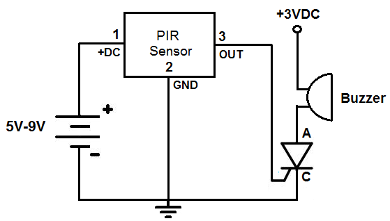
This is an alarm circuit that activates when motion is detected. Upon detection, the circuit triggers an alarm buzzer, which remains activated until the power is disconnected. This type of alarm circuit is commonly used to monitor areas for...
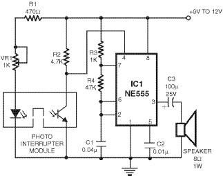
This smoke detector utilizes a 555 timer circuit along with common electronic components. The photo interrupter module serves as the smoke detection element, while the 555 timer is configured in astable mode to function as an audio frequency oscillator,...
This handy little circuit can tell the difference between darkness and light, making it very useful for switching on and off signs, porch lights or other things when it gets dark or light. More: R1 Adjusts sensitivity The circuit described...
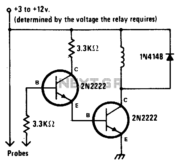
When the liquid level reaches both probes, the alarm is activated. When the water level recedes, the alarm is deactivated. The described circuit functions as a liquid level monitoring system utilizing two probes to detect the presence of liquid. The...
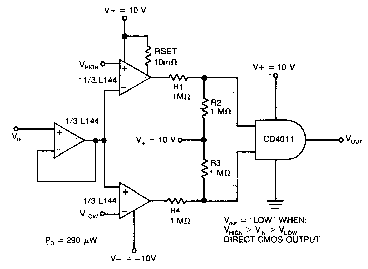
The detector utilizes three sections of an L144 and a DC4011 type CMOS NAND gate to create a very low power voltage monitor. If the input voltage, Vin, is above Vhigh or below Vlow, the output will be a...
The circuit diagram of the non-contact voltage detector is illustrated in Figure 1. It consists of two main components: an AC amplifier and an audio oscillator, which is based on the Schmitt trigger DD1.1 of the IC CD4093, along...
Warning: include(partials/cookie-banner.php): Failed to open stream: Permission denied in /var/www/html/nextgr/view-circuit.php on line 713
Warning: include(): Failed opening 'partials/cookie-banner.php' for inclusion (include_path='.:/usr/share/php') in /var/www/html/nextgr/view-circuit.php on line 713