
Noise generator circuit

The circuit's design emphasizes versatility in noise generation, making it suitable for various applications in sound synthesis, testing, and experimentation. The use of operational amplifiers ensures that the noise levels can be finely tuned, while the inclusion of filters allows for the shaping of the noise characteristics to meet specific requirements. The adjustable gain and graininess settings provide users with the ability to customize the noise output extensively, catering to both subtle and dramatic sound effects. This circuit is particularly beneficial for audio engineers and enthusiasts seeking to explore the boundaries of noise in creative and technical contexts.This circuit delivers a plentitude of noise, a veritable harvest of noise, yes, I dare say. an abundance of noise. Noise, noise and more noise. This circuit gives you white noise, pink-ish noise, high pass noise, grainy noise (with grainy adjust), and lastly adjustable random gates. Noise lovers take heart this board was made for you. In the Noise Cornucopia, the noise source is the reverse-biased emitter-base junction of Q1. We cut off the collector of Q1 so that it doesn`t act like an antenna picking up unwanted noise or EMI. The BVEBO (Emitter-Base Breakdown Voltage) is exceeeded thus the transistor is operating in avalanche mode.
More noise info can be found here: Random Electrical Noise: A Literature Survey - by Terry Ritter. The positive supply voltage is applied to the emitter of Q1 via R33 and R2, 470K resistors in series. Capacitor C18 filters the voltage applied to the emitter to reduce the possibility of supply ripple getting into the noise output.
Q1`s base is connected to the negative supply via R34, 10K resistor. This configuration results in more symmetry in the noise output. The noise generated at the EB junction of Q1 is capacitively coupled to the non-inverting input of U1-A which is biased to ground by R4 (2M) resistor. A gain of 48 is added by U1 and it`s output is fed capacitively to adjustable gain block U1-B. R5 is used to adjust the level of the noise at the output of U1-B to approximately +/-5V P-P. I found that just about any 2N3904 provided enough noise for this circuit but you may have to try a few to find the noisiest.
Try to find the one that needs the least gain out of the second gain block to give you the required +/-5V P-P. The 2N5172 is another good noise transistor choice but note the difference in the pinout if you use it.
U2-A and associated components comprise a high pass filter which gives the noise a very nice hissing quality. U2-B and associated components comprise a low pass filter which gives the noise a very nice Niagra Falls kind of sound.
The plain white noise is provided by the output of U1-B. The plain noise is applied to the inputs of window comparator U3-A/U3-B and associated components, and single sided comparator U4. The window comparator delivers high pulses (approx. -12V to +12V) when the noise exceeds the high window threshold voltage and low pulses (approx. +12V to -12V) when the noise exceeds the low window threshold voltage. The high and low pulses pass thru D1 and D2 respectively and are dropped across resistors R15 and R21 which act as a voltage divider to lower the level of the noise appearing on the Grainy Noise output.
At the cathodes of D1 and D2 spikes go from ground to -12 or ground to +12 depending on which side of the window is being exceeded. A passive high pass filter (C15 and R23) is applied to Grainy Noise and not too surprisingly results in the Hi-pass Grainy Noise output.
The Graininess adjust works by setting the size of the window for the window comparator. When wide (low setting), fewer noise peaks exceed the high and low voltage thresholds. As the window is narrowed more and more noise peaks exceed the high and low thresholds and thus more and more high and low pulses occur. This causes the noise to go from a few ticks to a full rainstorm/hailstorm/meteor shower. whatever. The noise applied to the single sided comparator U4 is slightly filtered by the passive low pass R26, C17, R27 and applied to the non-inverting input of U4.
The threshold for comparator U4 is set by the Gate Frequency pot R28. When noise peaks exceed the threshold set by R28 the output of U4 goes high (from approx. -12 to +12V). The positive excursions are fed through D3 and dropped on R29. These pulses provide a clock to the CD4024 7 stage binary counter. Since the clocks do not occur at a regular frequency the counter`s outputs change randomly. The mo 🔗 External reference
Related Circuits
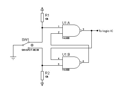
In most digital electronics projects that utilize various types of switches, switch bounces are frequently encountered. These are additional glitches that occur following the actual operation of the switch. These small pulses can disrupt the proper functioning of the...

A Siemens SLB0586A IC enables the creation of a straightforward touch-controlled dimmer circuit. This circuit regulates a triac AC switch, allowing control of loads ranging from 10 to 400 W. The Siemens SLB0586A integrated circuit is designed to facilitate the...
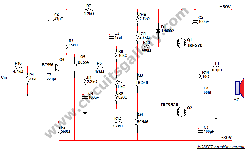
This is a MOSFET transistor-based power amplifier circuit that operates within a voltage range of +35V to -35V. The input voltage is pre-filtered and pre-amplified before being applied to the MOSFET switch. The pre-audio amplifier consists of a differential...
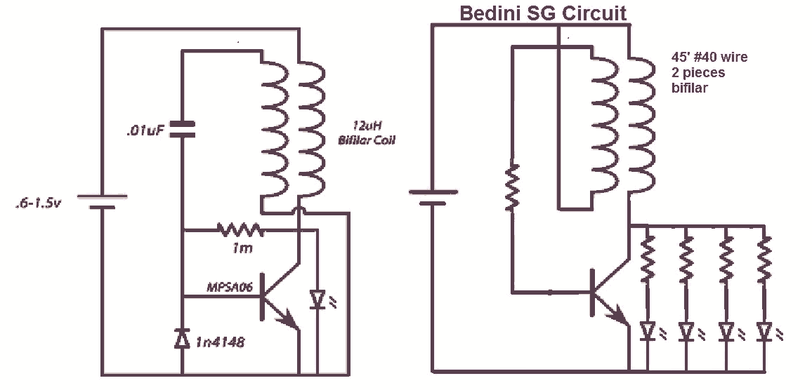
It would be beneficial to obtain schematics of the Joule Thief and Bedini oscillator circuit connections. This is an area that has not been previously explored. The schematic on the left was sourced from the Energetic Forum, while the...

The circuit is designed to fit snugly, eliminating the need for adhesive. It is recommended to test the fit multiple times, making incremental adjustments until a snug but movable fit is achieved. The entire circuit should be placed inside...
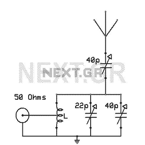
The antenna tuning circuit can accommodate 1/2 wave length antennas or higher, for input resistances of 50 Ohms which make it suitable for CB (Citizen Band) transceivers. C1 is for fine tuning and C2 is just for tuning. Turning...