
Low Voltage Preamplifier
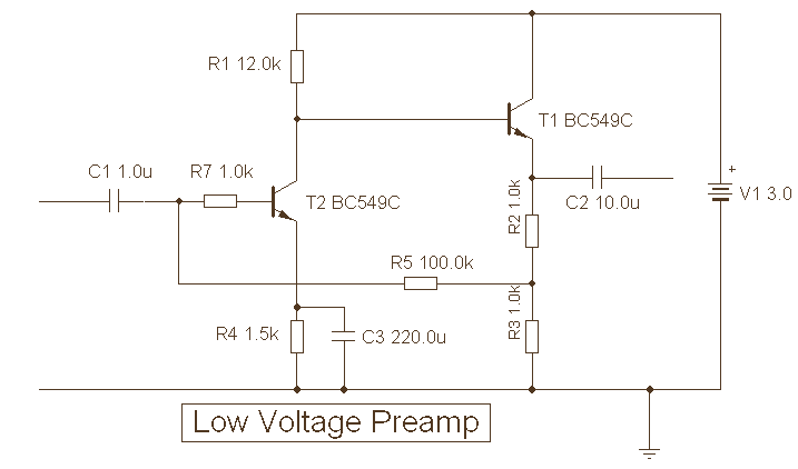
The second transistor, T2, realizes the full voltage gain of the amplifiers. For the operation to have low noise, the collector current of T2 is maintained at approximately 70uA. T1, the first transistor, merely buffers T2. It operates in emitter follower mode, which provides a good low output impedance. The overall signal-to-noise (S/N) ratio, which is measured at the output, has been indicated below, but no specific values are provided in the original description.
To further elaborate, the low voltage design of this audio preamp is advantageous in applications where power consumption needs to be minimized. The use of direct coupling between the transistors ensures a high level of frequency response, making the preamp suitable for a wide range of audio signals. The closed-loop feedback system helps to maintain the stability of the system, which is critical in maintaining the quality of the amplified signal, especially in variable temperature conditions.
The emitter follower mode of operation of T1 ensures that the output signal follows the input voltage, thus providing a high input impedance and low output impedance. This characteristic makes the circuit an excellent choice for impedance matching applications.
The low noise operation of the circuit is achieved by keeping the collector current of T2 at about 70uA. This reduces the chance of thermal noise, which can degrade the quality of the output signal. The overall S/N ratio would give an indication of the quality of the output, with a higher ratio indicating a cleaner, higher fidelity signal. However, without specific values, it is difficult to assess the exact performance of this preamp.This is a special low voltage version of my audio preamp. T1`s emitter voltage is biased close to half supply voltage (1.5V) to allow for maximum output voltage swing. Both transistors are direct coupled and have closed loop feedback to aid temperature stability. T2 realizes the amplifiers full voltage gain, and for low noise operation, T2 collector current is about 70uA.
T1 merely buffers T2 and operates in emitter follower mode providing a good low output impedance. The overall S/N ratio measured at the output is shown below: 🔗 External reference
Related Circuits
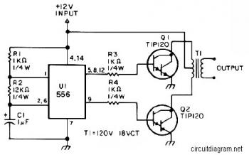
The first section of the 555 timer is configured as an astable oscillator, with resistors R2 and capacitor C1 determining the frequency. The output is available at pin 5. The second section is set up as a phase inverter,...
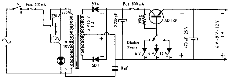
Such supplies are often realised with dedicated integrated circuits nowadays but it's still interesting to give a look at old designs to understand the basics. The description outlines the evolution of power supply designs in electronics, emphasizing the transition from...
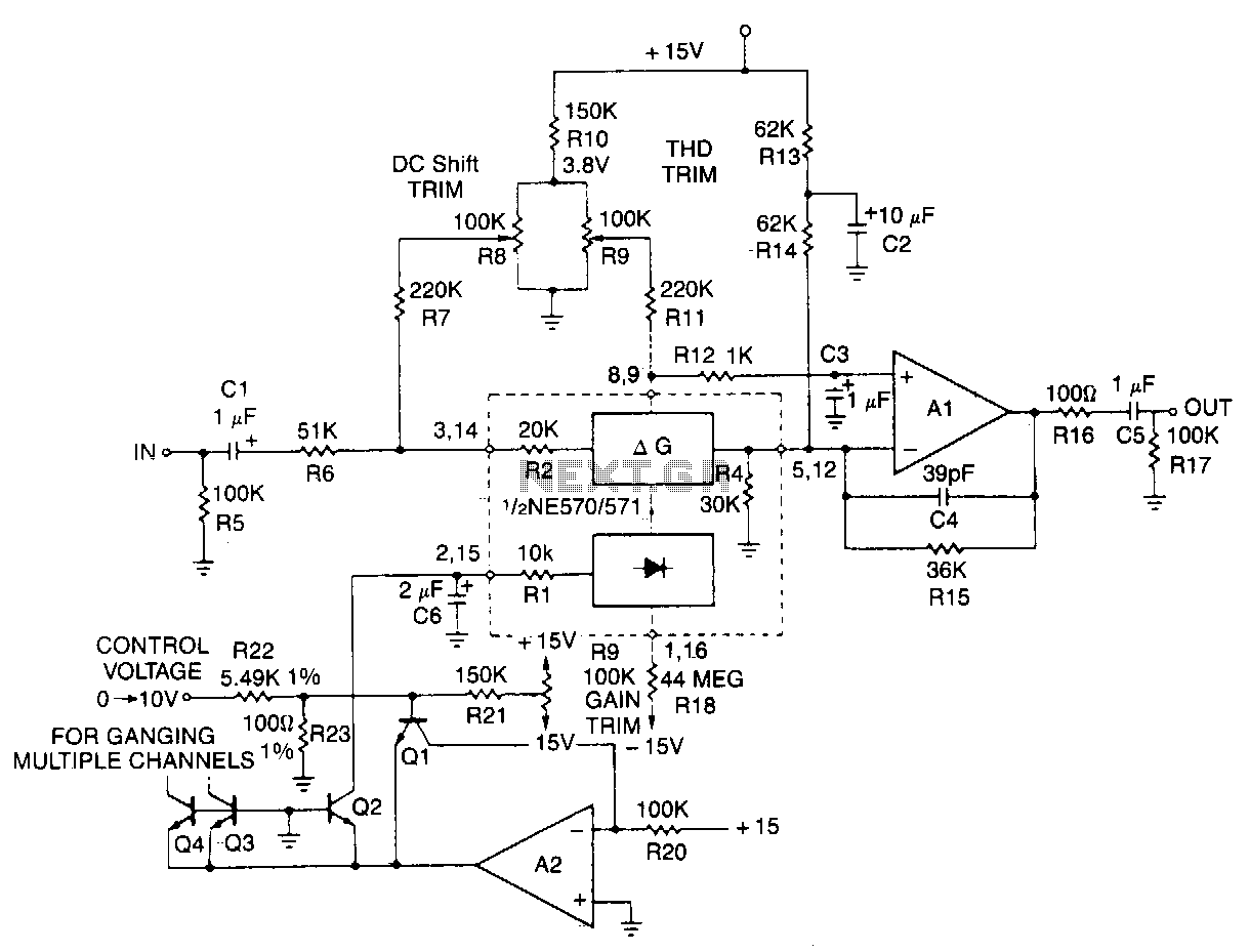
This typical circuit utilizes an external operational amplifier for improved performance, along with an exponential converter to achieve a control characteristic of -6 dB per volt. Trim networks are incorporated to eliminate distortion and offset, as well as to...
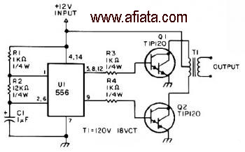
The first section of the 555 timer is configured as an astable oscillator, with R2 and C1 determining the frequency. The output is accessible at pin 5. The second section functions as a phase inverter, with its output available...
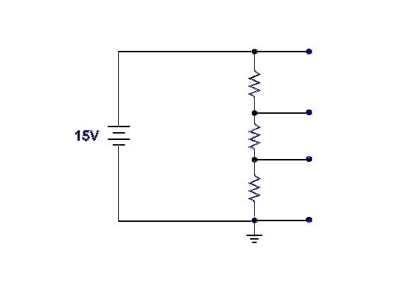
Ground serves as a reference point for the voltage divider, with each successive point above ground indicating the voltage drop across the circuit. For example, with a 15-volt input and 5K ohm resistors, the voltage taps would measure 5,...
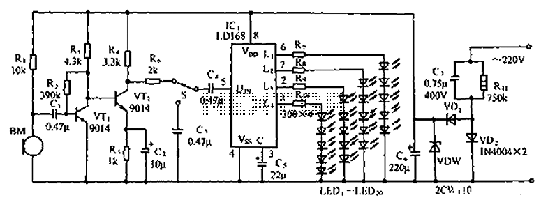
The circuit depicted in the figure involves the LD168, which functions as a sound level indicator for tape recorder speakers. It features four outputs capable of directly driving multiple light-emitting diodes. Additionally, the device can be activated by a...