
op amp How does this OP-AMP offset voltage measuring circuit work
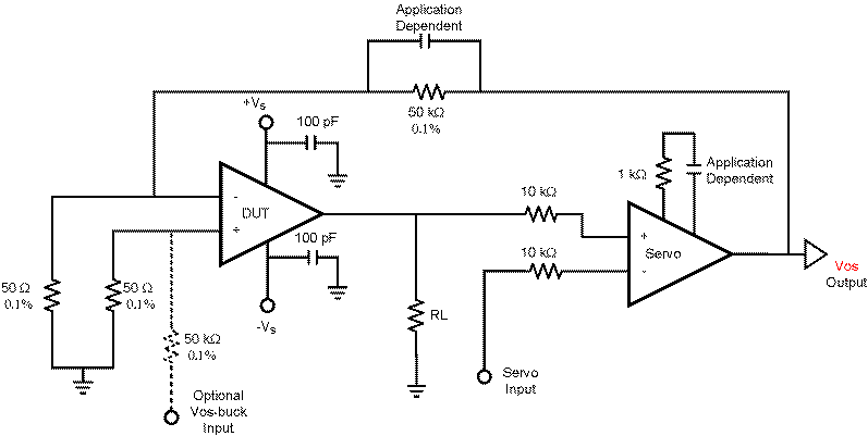
The circuit utilizes two LT1001 operational amplifiers configured to create a precision voltage follower and a high-gain amplifier setup. The primary function of this arrangement is to ensure that the output of the DUT accurately reflects the input voltage applied at the Servo Input, with a gain determined by the feedback configuration of the Servo OP-AMP.
The first LT1001 serves as the Servo amplifier, which stabilizes the output by continuously adjusting its output to maintain the voltage at its non-inverting input equal to the voltage at its inverting input. The feedback network, consisting of resistors, sets the gain of this amplifier. When a voltage is applied to the Servo Input, the Servo OP-AMP adjusts its output, which in turn influences the DUT.
The second LT1001 is configured as the DUT. It receives the output from the Servo OP-AMP and produces an output voltage that is a function of its input voltage, offset voltage, and any gain errors present. The offset voltage (VOS) is a critical parameter in this circuit, as it directly impacts the accuracy of the DUT's output. It is important to note that the offset voltage is amplified by the loop gain of 1000, thus resulting in a significant effect on the output voltage.
The circuit's design ensures that the offset voltage introduced by the DUT is minimized due to the high loop gain of the Servo amplifier, which effectively reduces the impact of VOS on the final output. The interaction between the two OP-AMPs creates a feedback loop that enhances stability and precision, making this configuration suitable for applications requiring high accuracy and low offset errors.
In summary, the circuit's operation hinges on the interplay between the Servo OP-AMP and the DUT, with careful consideration given to the effects of offset voltage and gain errors. Understanding the role of VOS as a voltage source is essential for fully grasping the dynamics of this circuit and its intended application.I`ve built this circuit with two LT1001 s and the output of the OP-AMP saturates to +5V. I used +5V and GND for the supplies. In the page, it says that if +1V is applied to the "Servo Input", the output of the DUT will be +1V. I can understand that since the Servo OP-AMP will try to make its both inputs the same by changing its output voltage accordingly. Since there is almost no voltage drop across 10k in the non-inverting input of the Servo OP-AMP, output of the DUT will be +1V. For example, say the DUT has an offset voltage of +500 V and NO gain errors and the Servo Input is set to +2.
5V. The DUT`s output will now be set to 2. 5V and VOS will be at +500 mV regardless of the Servo Input setting. Any gain error would be summed in along with the offset voltage, and the result is multiplied by the loop gain (1000). With the Servo Input grounded the circuit basically functions as a "gain of 1000" test circuit. The Servo amp contributes very little in the way of offset errors (the servo amp`s offset is divided `down` by the loop gain).
I couldn`t understand why Vos (output of the Servo OP-AMP ) will be at +500mV (that is the gain multiplied by the offset voltage of the DUT) Both OP-AMPs are in each others feedback loop, however, DUT is in the positive feedback loop of the Servo. Why is that It would be great that you include Vos as a voltage source when you are explaining. 🔗 External reference
Related Circuits
An automatic recording telephone interface circuit is presented, featuring an automatic answering and recording function that requires a reprovisioning or a small solid-state recording chip. The circuit is straightforward, with a quiescent current of less than 20 µA, allowing...
The AD654 is a monolithic voltage-to-frequency (V/F) converter that comprises an input amplifier, a precision oscillator system, and a high-current output stage. A single resistor-capacitor (RC) network is all that is needed to configure any full-scale (FS) frequency up...
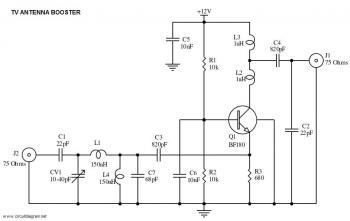
This is a straightforward circuit for a UHF band TV antenna booster that provides a gain of 15 dB. This low-cost antenna booster is simple and easy to construct. The UHF band TV antenna booster circuit is designed to enhance...
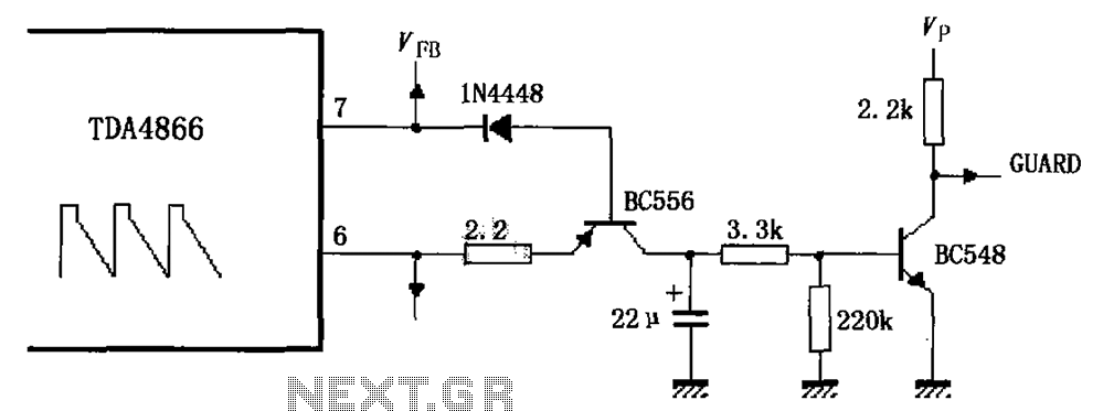
As illustrated in FIG TDA4866, the circuit consists of an external signal generator circuit protection. The internal protection circuit's role is to manage control, while the external protection circuit performs its functions. During normal operation, the vertical amplitude of...
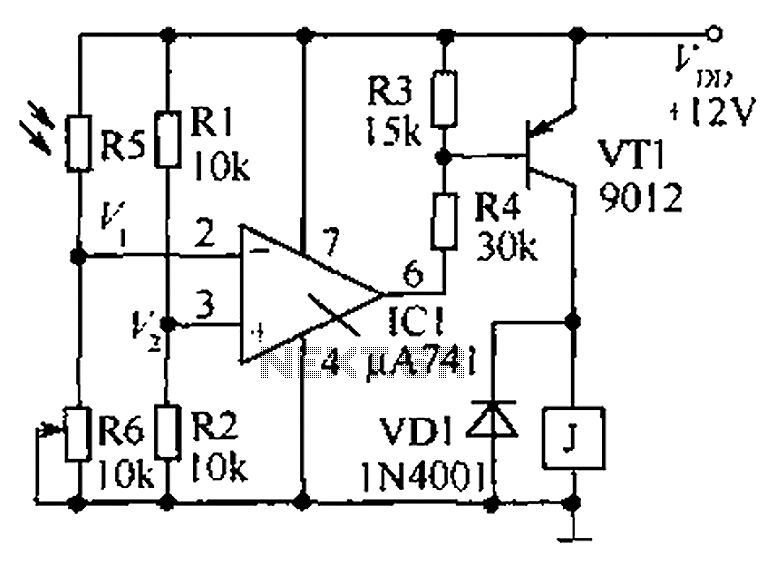
The circuit functions as a precision bright light control circuit, operating independently of variations in power supply voltage and ambient temperature. Resistors R1, R2, R6, and the photosensitive resistor R5 form a two-arm Wheatstone bridge. The precision bright light control...
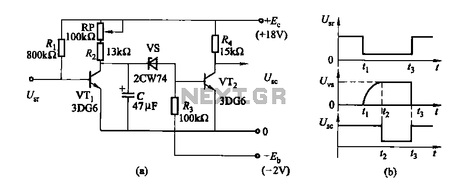
The delay time ranges from 0.5 to 3.5 seconds, which can be adjusted using the potentiometer RP to modify the delay duration. The circuit utilizes a timing mechanism that allows for the adjustment of delay intervals between 0.5 seconds and...