
Low-volts alarm

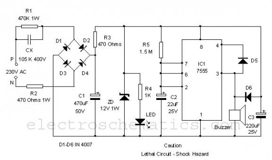
The circuit operates by utilizing a zener diode to establish a reference voltage level. When the input voltage falls below this reference, the zener diode conducts, signaling the alarm circuit to activate. The alarm is typically implemented using a simple piezoelectric buzzer or a similar sound-emitting device.
The RC time constant, determined by the resistor and capacitor values, influences the frequency and duration of the alarm sound. In this circuit, the 39 kΩ resistor in combination with the 0.01 μF capacitor creates a time constant of approximately 0.39 milliseconds, which affects the oscillation frequency of the alarm tone produced. The resulting sound can be adjusted by changing these component values, allowing for customization based on user preference.
This voltage monitor is particularly advantageous in battery management systems where low power consumption is essential. The circuit's design ensures minimal energy draw during its idle state, making it ideal for applications where battery life is a critical factor. The simplicity of the design allows for easy integration into existing systems, providing a reliable solution for voltage monitoring in various electronic applications.This inexpensive dc supply-voltage monitor sounds a warning when the voltage falls below a preset value. It is ideal for monitoring rechargeable batteries since it draws only a few microamperes when not sounding.
The voltage at which the alarm sounds is determined by the zener diode. When the voltage falls below the zener voltage, the alarm sounds. The alarm tone is determined by the RC time constant of the 39 k resistor and 0.01 mf capacitor. 🔗 External reference
Related Circuits

An auto horn operates as a speaker within a limited audio-frequency range. This circuit utilizes a 555 timer configured as an oscillator to drive an MJE34 transistor, which subsequently activates the horn. Normal horn operation is maintained through the...
The loop can consist of any type of hookup wire, with a maximum resistance of approximately 90K ohms. Utilizing very thin wire (such as 40AWG) will create a highly sensitive trip wire; however, this will reduce the distance over...
Simple construction, reliable operation, very small power consumption, and, most of all, small size. I started with CMOS logic gates, but was soon forced to abandon the concept after a few unsuccessful (and far too complicated) attempts. Then I...

The following circuit illustrates a Sun Up Alarm Light Alarm Circuit Diagram. This circuit is based on the 555 Integrated Circuit (IC). Features include simplicity and cost-effectiveness. The Sun Up Alarm Light Alarm Circuit employs the 555 timer IC in...
This circuit utilizing a 555 timer IC can be used as an alarm system to prevent the theft of your luggage, burglars breaking into your house, etc. The alarm goes ON when a thin wire, usually as thin as...
This is a simple power resumption alarm circuit that can be installed within the switch box. It emits beeping sounds when power is restored following a power outage. The power resumption alarm circuit serves as a practical solution for alerting...