
LPT Circuito for Switch a Remote Coax
The Ameritron RCS-10 is a remote coax switch designed for amateur radio applications, allowing users to control multiple antennas or feedlines from a single location. A typical circuit for managing the RCS-10 involves the integration of a control circuit, a power supply, and the coax switch itself.
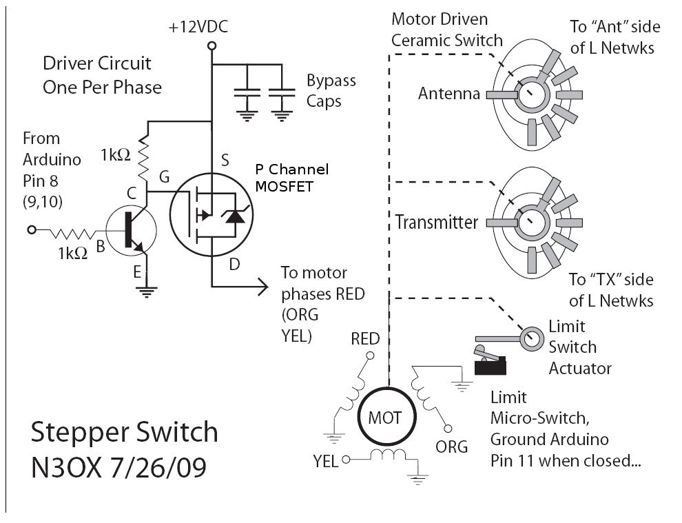
The control circuit usually consists of a microcontroller or a simple relay-based system that receives input from a user interface, such as a switch or remote control. The user interface can be designed to allow the selection of different antennas, and it sends signals to the control circuit to activate the appropriate relay.
The power supply for the RCS-10 should be capable of providing the necessary voltage and current to operate the switch and control circuitry. Typically, a 12V DC power supply is used for this purpose. It is important to ensure that the power supply is stable and can handle the load of the coax switch to prevent any operational issues.
The coax switch itself consists of multiple coaxial connectors and internal relays that direct the RF signals from the selected antenna to the transceiver. The relays should be rated for the frequency range and power levels expected in typical amateur radio usage.
When designing the schematic, it is crucial to include protection circuits such as diodes to prevent back EMF from damaging the control circuitry, especially if relays are used. Additionally, proper grounding and shielding techniques should be employed to minimize RF interference and ensure reliable operation.
In summary, a comprehensive circuit design for managing the Remote Coax Ameritron RCS-10 includes a control circuit, a stable power supply, and the coax switch, all while incorporating necessary protective measures to ensure efficient and safe operation in amateur radio applications.I need some information about a circuito to manage ma Remote COax Ameritron RCS-10, I can`t find on google some information about a diagram.. 🔗 External reference
Related Circuits
There is an interest in creating an interactive LED game board or a "Stargate" DHD-type sci-fi prop, where each tile is illuminated from below by either a single white LED or an RGB combination. The goal is to make...
For the limit switches on a custom 3D printer being designed, contactless sensors will be utilized. Hall effect sensors, which are sensitive to magnetic fields, have been selected. There are three types of these sensors: the omnipolar hall sensor,...
FGDF-3 is a three-phase low-temperature iron plating power commutation control switch and electronic circuit. The KGDF-3 serves as a low-temperature iron plating power supply device, incorporating the characteristics of a single-phase low-temperature iron plating power supply. This design facilitates...
Remote controls are often needed to manage various electric devices. There are several types of remote controls available, including infrared, RF (Radio Frequency), and SMS. Basic short-range remote controls primarily utilize infrared and RF technology. A limitation of infrared...
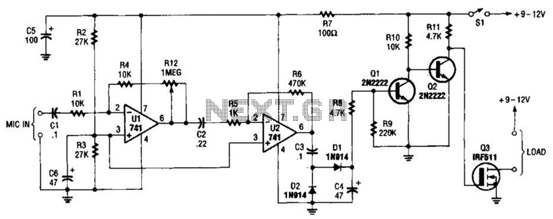
The audio-controlled switch utilizes a pair of 741 operational amplifiers, two 2N2222 general-purpose transistors, a hexFET, and several supporting components to create a circuit capable of activating devices such as a tape recorder, a transmitter, or virtually any other...

The receiver section was not illustrated as it is considered standard. The TRIAC switch section depicted below can be controlled using standard 4000 series CMOS logic. The TRIAC switch section operates by utilizing a TRIAC (Triode for Alternating Current) component,...
Warning: include(partials/cookie-banner.php): Failed to open stream: Permission denied in /var/www/html/nextgr/view-circuit.php on line 713
Warning: include(): Failed opening 'partials/cookie-banner.php' for inclusion (include_path='.:/usr/share/php') in /var/www/html/nextgr/view-circuit.php on line 713