
hall effect switch

The circuit design incorporates the Allegro A3144 unipolar Hall effect sensor, which is positioned to detect the proximity of a magnet for limit switch applications in a 3D printer. The sensor's output is connected to the gate of an N-channel MOSFET, which controls the off-state LED, while the triggered LED is connected directly to the sensor output. This design allows for visual feedback of the sensor's status. The SMD components are arranged to optimize space and facilitate soldering on a breadboard, which is beneficial for prototyping.
The 74LVC1G58 logic chip can be configured to serve as an inverter, providing an alternative method for driving the LEDs with fewer components. This chip's output capability of ±24 mA ensures that both LEDs can be driven effectively. The choice of a JST ZH connector allows for compact connections while maintaining reliability in the circuit. The PTFE coated wire used for connections enhances durability and minimizes the risk of damage during soldering.
The overall dimensions of the board, along with the mounting hole for an M3 bolt, contribute to a compact and efficient design suitable for integration into a 3D printer. The inclusion of hysteresis in the A3144 sensor enhances the stability of the circuit by preventing false triggering due to minor fluctuations in magnetic field strength. The final layout not only meets the functional requirements but also optimizes the use of space, making it an effective solution for implementing limit switches in a custom 3D printer design.For the limit switches on a custom 3D printer I`m designing, I want to try out some contactless sensors. I have chosen to use hall effect sensors, which are sensitive to a magnetic field. There are three different types of these sensors available. First, there`s the omnipolar hall sensor, which turns on when a magnet comes in its vicinity. Next is the unipolar one, which turns on as long as a specific magnetic pole is close enough, which pole depends on the sensor. Finally, there`s the bipolar hall effect sensor, which latches on when one pole comes close and only turns off when it senses the other pole.
The sensors that I am using for my circuit is an Allegro A3144, an unipolar sensor. These are no longer manufactured, however eBay is chock full of them and they can be had for less than ‚¬0. 20 each. They come in a miniature TO-92-like package, as seen in the picture below. As a visual indication of the sensor`s status, I want two LEDs, one each for the triggered and off state.
Since the A3144 has an open collector output, driving a LED from the output is only possible when the sensor is triggered. In order to drive both LEDs either a buffer or an inverter is required. One option is to use an N-channel MOSFET for the off LED and connect the triggeredLED straight to the A3144`s output.
Apart from the MOSFET, this would also require a resistor to the MOSFET`s gate. A alternative which uses less parts is the versatile 74LVC1G58. This is a configurable logic chip with 3 inputs, which has ±24 mA output drive and comes in a tiny SOT23-6 package. Best of all: when configured as an inverter, the pins are grouped together such that the chip can be soldered on a standard breadboard.
You can find the schematic for my simple hall effect switch below. I used SMD components for everything, except the hall effect sensor and the connector. Although tiny, all of the SMD components can be soldered without any problem on a standard breadboard. The dual LED comes in a 1210 SMD package, all resistors and capacitors are 0603 format. The connector is a tiny JST ZH and had to be cut up a bit, so that the leads could be forced into the breadboard.
I didn`t bother with a custom board, due to the small number of components. Connections are made with solid core 30 AWG (‰ 0. 25 mm diameter) PTFE coated wire. I really like the PTFE coating for SMD work, since it won`t melt when heated by a soldering iron, so you don`t get accidental short circuits. In the middle of the board is a mounting hole for an M3 bolt. The final board size is 19 mm x 14 mm. For fun I routed a custom two-layer layout (all components on the top layer) which came out to 17 mm x 11.
5 mm, so this breadboard layout is pretty close to the minimum area. Below is a picture of the board on a 50c coin for size comparison. The circuit triggers very reliably for a handful of magnets I have lying around. The A3144 has build-in hysteresis, which is really nice. Without it, the output would oscillate when a magnet is just at the trigger distance. Although not necessary in this case, the 74LVC1G58 has Schmitt-trigger inputs, so you could use an analog output hall sensor instead of the A3144 and would also get hysteresis on the output without having to change anything else. See the image below for the circuit both in off and triggered state. 🔗 External reference
Related Circuits
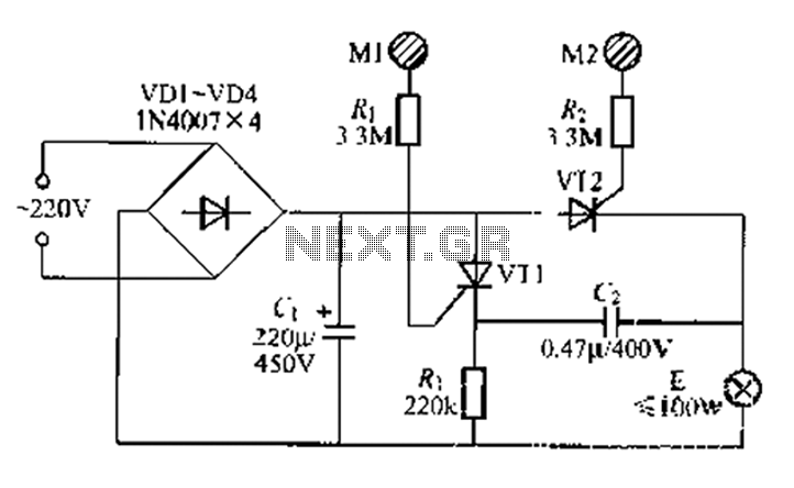
A circuit configuration features a relatively new strong key touch-state switch. Normally, the thyristors VT1 and VT2 are in the off-state, allowing minimal current to pass through the lamp F. At this point, the capacitance C comes into play....
This line voltage power controller connects a DC control voltage or microprocessor logic output to an AC load. By adding a filter capacitor to the input resistors, the circuit can be controlled by a duty-cycle modulated square wave with...

This circuit is a simple remote-controlled relay capable of switching lamps or other devices. D1 can be a phototransistor, LDR, or an infrared transistor. The circuit is controlled using an IR remote, similar to a TV remote control, when...
This is a single channel (on / off) universal switch that may be used with any Infra Red remote control using 36-38kHz. (This is a very common remote handset frequency). Any "button" of any remote control may be used...
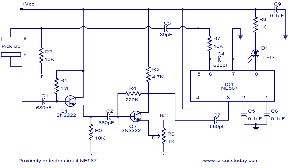
A simple proximity detector circuit utilizing the NE567 integrated circuit (IC). The circuit activates an LED when an object approaches the sensor. The NE567 is a versatile phase-locked loop (PLL) device commonly used for applications such as proximity detection due...
National Semiconductor has been designing and manufacturing integrated circuits (ICs) for switch-mode power supplies for many years. The application of these devices is typically straightforward, supported by comprehensive documentation. A common example of a switch-mode power supply is based...