
LT3083 current limiting
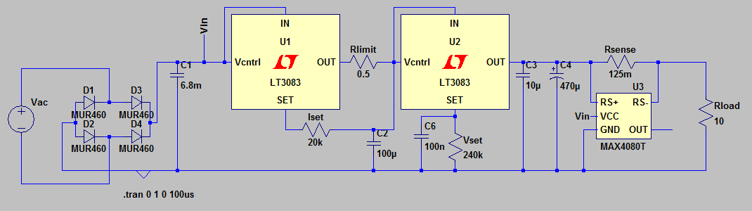
The described circuit employs two LT3083 voltage regulators to achieve stable output voltage and current control. The LT3083 is a low-dropout linear voltage regulator known for its high accuracy and low noise, making it suitable for precision applications. The use of analog control through potentiometers for setting current (Iset) and voltage (Vset) allows for fine-tuning of the output parameters, while the digital readouts provide real-time monitoring of the voltage and current levels.
In this configuration, the potentiometers are modeled as resistors in LTSpice simulations to account for the absence of a potentiometer component. Each potentiometer is connected to a 50 µA current source from the LT3083, ensuring that the adjustments made to Iset and Vset are effective and responsive. The choice of a 0.5-ohm resistor as Rlimit serves a dual purpose: it acts as a current sense resistor and facilitates current limiting functionality. By employing a 5x gain amplifier, the design aims to minimize the voltage drop across Rsense, which can otherwise introduce inaccuracies in the output voltage.
The issue of ripple between the regulators when not in current limit mode indicates the need for careful design consideration. The left LT3083's tendency to output maximum voltage can lead to instability and undesirable ripple effects. To mitigate this, additional filtering or feedback mechanisms may be necessary to stabilize the output and reduce the influence of input ripple. This could involve implementing capacitors at the output or utilizing additional components to enhance the regulation performance under varying load conditions.
In summary, the circuit design focuses on achieving precise voltage and current control through the integration of LT3083 regulators, potentiometers for adjustment, and a current sensing mechanism to ensure safe operation. Addressing the ripple issue will be crucial for maintaining stable performance and reliability in the overall system.I`m using regular analog control via pots, though will use digital readouts of voltage/current. Anyhow. I HAVE watched the PSU videos, but at least in simulations I couldn`t get the single-LT308x with the transistor limiter to work properly (one, it didn`t go to 0, so a shorted output causes >2 amps to flow! - and two, it tended to oscillate a bit now and then). I`ve almost decided to go a simpler but more expensive route and simply use two LT3083s. I attached the LTSpice circuit, though without the MAX4080T current sense amp, since that component is in a separate file on my computer. It didn`t affect these questions whatsoever, though. Also, note that "Iset" and "Vset" are potentiometers wired as rheostats; I model them as resistors in LTSpice since there`s no built-in pot component.
In each case, they`re controlled by a 50 µA current from the LT3083. What I`d like to do is to use Rlimit (0. 5 ohms) as the current sense resistor (with a 5x gain amp instead, of course), to eliminate the extra 250 mV drop over Rsense at the output. The reason I "can`t" right now is that there is a lot of ripple between the regulators when the current-limit mode isn`t active; the left LT3083 simply outputs as high a voltage as it can, which lets the input ripple through unchanged:
🔗 External reference
Related Circuits
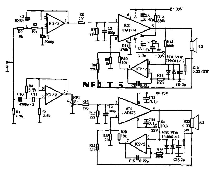
The mechanical and electrical schematic in Figure 5 illustrates a simple circuit comprising several components. The first component is an electronic crossover section utilizing the NE5532 operational amplifier, which is known as the "Emperor of the op-amp." This section...
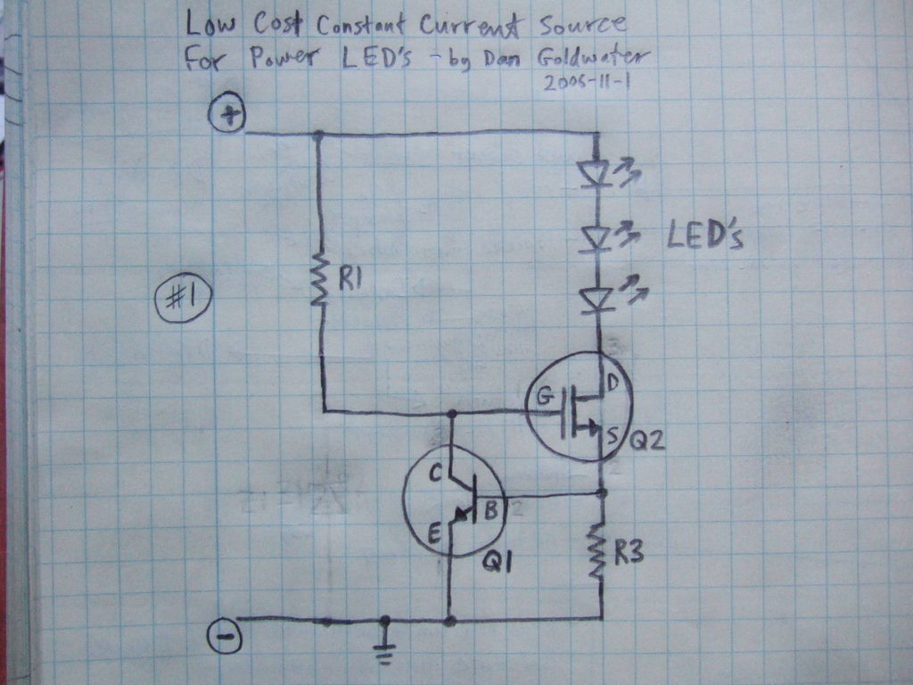
Here is a simple and inexpensive ($1) LED driver circuit. The circuit functions as a constant current source, ensuring that the LED maintains consistent brightness. The LED driver circuit is designed to provide a stable current to the LED, which...
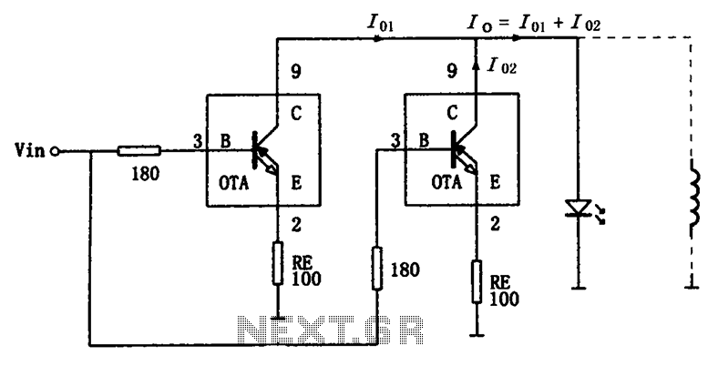
The high-speed parallel current drive circuit utilizes the OPA660 operational transconductance amplifier (OTA). An input signal, Vin, is connected to a 180-ohm resistor equivalent device at the base (pin 3) of the OPA660. The collector (pin 8) is directly...
This discrete voltage regulator features capabilities equivalent to modern voltage regulator integrated circuits (ICs). While constructing a discrete version may not be cost-effective, studying the schematic diagram provides valuable insights into its operation. The circuit includes a resistor of...
In this circuit, an LM339 quad voltage comparator is utilized to generate a time delay and control a high current output at low voltage. Approximately 5 amps of current can be sourced using a pair of fresh alkaline D...
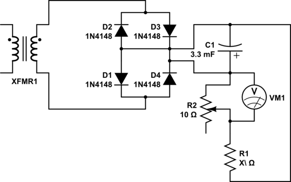
Connect the 25VAC output to a diode bridge with a capacitor (3300uF - 25V) to the positive and negative pins to eventually obtain 25VDC. The goal is to reduce the 25VDC to 17VDC. A voltage divider with a variable...