
Low Voltage High Current Time Delay Circuit
The circuit under discussion employs the LM339, a quad comparator known for its ability to operate in low voltage conditions while providing reliable performance. The configuration of three comparators in parallel enhances the current-driving capability, allowing the circuit to effectively control high power loads. The PNP transistor (2N2905) acts as an intermediary switch, amplifying the output from the comparators to drive the TIP35 NPN transistor, which is capable of handling significant current loads.
The fourth comparator's role in generating a time delay is crucial for applications requiring controlled timing sequences. The voltage divider composed of 36K and 62K resistors ensures that the voltage at the comparator’s positive input is set correctly, allowing for precise timing control. The choice of a 50µF capacitor paired with a 100K variable resistor provides flexibility in adjusting the time delay, making the circuit adaptable to various applications.
For users needing to adjust the timing, the variable resistor allows for fine-tuning of the delay period. Reducing the resistance will shorten the delay, while increasing it will lengthen the timing. The capacitor's value also plays a significant role in this timing equation, where smaller capacitors will yield shorter delays and larger capacitors will extend the delay period.
In scenarios where the circuit is required to operate at higher voltages, careful consideration must be given to the 10-ohm resistor, as it must be increased to maintain circuit stability and performance. This proportional adjustment ensures that the current remains within safe limits, preventing damage to the components while optimizing the circuit's functionality. Overall, this design exemplifies a versatile approach to timing and current control using readily available components.In this circuit a LM339 quad voltage comparator is used to generate a time delay and control a high current output at low voltage. Approximatey 5 amps of current can be obtained using a couple fresh alkaline D batteries. Three of the comparators are wired in parallel to drive a medium power PNP transistor (2N2905 or similar) which in turn drives a
high current NPN transistor (TIP35 or similar). The 4th comparator is used to generate a time delay after the normally closed switch is opened. Two resistors (36K and 62K) are used as a voltage divider which applies about two-thirds of the battery voltage to the (+) comparator input, or about 2 volts. The delay time after the switch is opened will be around one time constant using a 50uF capacitor and 100K variable resistor, or about (50u * 100K) = 5 seconds.
The time can be reduced by adjusting the resistor to a lower value or using a smaller capacitor. Longer times can be obtained with a larger resistor or capacitor. To operate the circuit on higher voltages, the 10 ohm resistor should be increased proportionally, (4. 5 volts = 15 ohms). 🔗 External reference
Related Circuits
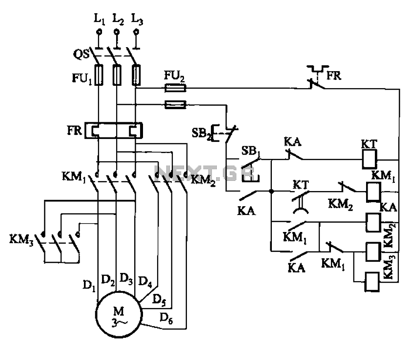
The circuit depicted in Figure 3-99 illustrates a low start-up mechanism for a motor, which transitions to high-speed operation automatically. The start-up process is facilitated by a shaped connection, while the transition to high-speed operation is managed by a...
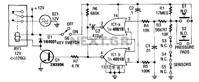
In this circuit, IC1A and IC1B serve as a monostable multivibrator. Any input from the sensors SI through S5 triggers IC1A to produce a logic low signal, which activates IC1B, turning on Q1 until the capacitor C3 discharges through...
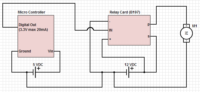
The objective is to control a 12 VDC device (on/off) from a microcontroller using a relay card. The relay requires a 12 VDC operating power supply. To achieve the control of a 12 VDC device using a microcontroller and a...
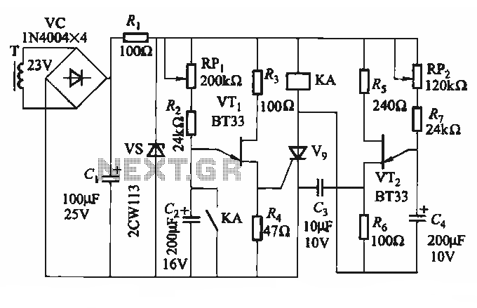
The circuit depicted in Figure 3-69 is designed for applications requiring frequent timing control for motor reversing operations. In this configuration, thyristors V1, V2, and V7 are utilized for positive control of motor rotation, while thyristors V3, V4, V5,...
This circuit features a microphone and preamplifier that take precedence over any other audio signal, functioning similarly to a one-way intercom. When the push-to-talk switch is activated, the main amplifier switches from music playback to the voice signal. Essentially,...
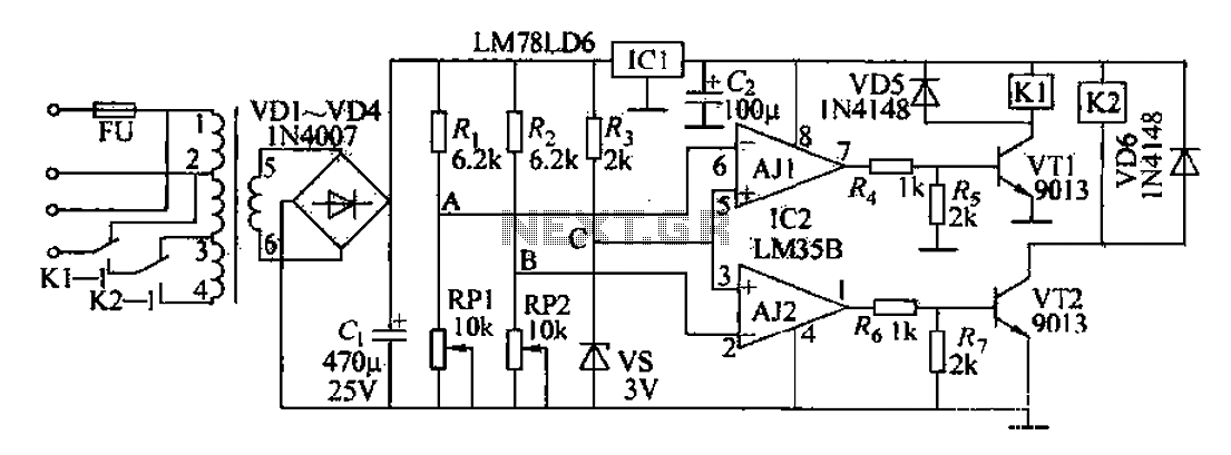
The AC power supply circuit primarily consists of a power supply, a reference voltage, a voltage comparator for sampling, and several other components. It includes a transformer for the input, an autotransformer tap for the control power supply circuit,...
Warning: include(partials/cookie-banner.php): Failed to open stream: Permission denied in /var/www/html/nextgr/view-circuit.php on line 713
Warning: include(): Failed opening 'partials/cookie-banner.php' for inclusion (include_path='.:/usr/share/php') in /var/www/html/nextgr/view-circuit.php on line 713