
Parallel high-speed current driver circuit diagram OPA660
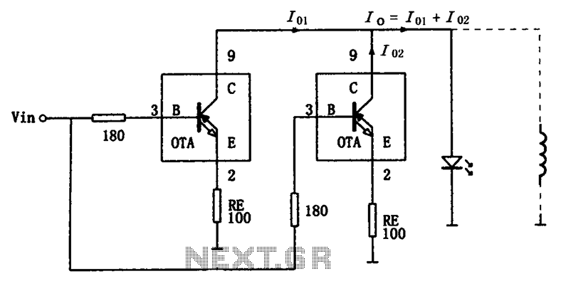
The high-speed parallel current drive circuit is designed for applications that require precise control of output current while maintaining high-speed performance. The OPA660 OTA is specifically chosen for its ability to deliver significant output current, making it suitable for driving various loads, including capacitive and resistive components. The input signal, Vin, is effectively conditioned by the 180-ohm resistor, which mitigates the risk of self-oscillation that could compromise circuit stability. This resistor also plays a crucial role in shaping the frequency response of the amplifier, ensuring that the circuit operates efficiently across the desired frequency range.
In parallel configurations, the OPA660s work cohesively to provide the necessary current without exceeding individual device limits. This approach not only enhances the overall output capability but also ensures redundancy, as the failure of one OTA does not significantly impact the performance of the entire circuit. The inclusion of the negative feedback resistor, RE, contributes to the circuit's robustness by stabilizing the gain and improving linearity. However, it is essential to select the appropriate value for RE, as it directly influences the transconductance of the OTA, thereby affecting the output current. The careful design of this circuit allows for versatility in applications, from audio amplification to signal conditioning in communication systems, where high-speed and high-current drive capabilities are paramount. As shown for the high-speed parallel current drive circuit. Input signal Vin have been added 180 resistor equivalent device OPA660 special OTA transistor base B (pin 3), the co llectors C (pin 8) connected directly, and connected with the load, while providing current to the load, thus the current flowing through a single OTA twice the load, because the OTA OPA660 maximum output current of 15mA, while the parallel circuit provides a maximum output current up to 30mA. When you need more current, multiple OPA660 op amps in parallel, in order to obtain the desired load current.
Input (B pole) 180 external resistor having a limiting effect, while preventing self-oscillation occurs amplifier and reduce the phenomenon peaking frequency characteristics. Connected to the emitter of the negative feedback resistor RE (tens of ohms to several hundred ohms) can increase the number of dynamic index linear amplifier input impedance and stability, but the OTA transconductance will decline, it can be seen, RE appropriately changing the resistance can adjust the size of the output current.
Related Circuits

Figure 1-122 is a dedicated high-fidelity surround sound processing integrated circuit (IC) TDA3810 circuit that manages surround sound. The stereo signal is processed through input coupling capacitors C1 and C2. The internal buffer amplifier handles the left and right...
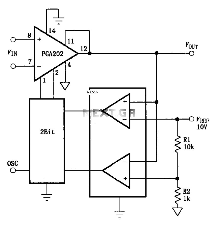
The automatic range switching circuit consists of PGA202, comparators, and counters, as illustrated in the figure. The comparator at the output compares VOUT with VREF. When VOUT exceeds 10V, the comparator generates a low signal, causing the up/down counter...
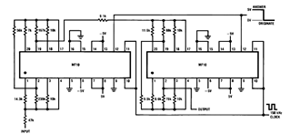
Later, there will be applications including a Basic Circuit Description, Block Diagram of the MF10, Programmable Dual Clock Generator, Butterworth Lowpass Filter, MF10 as an Input Filter and Sample/Hold, Generating Quadrature Sine Waves, and the Non-Inverting Integrator used in...
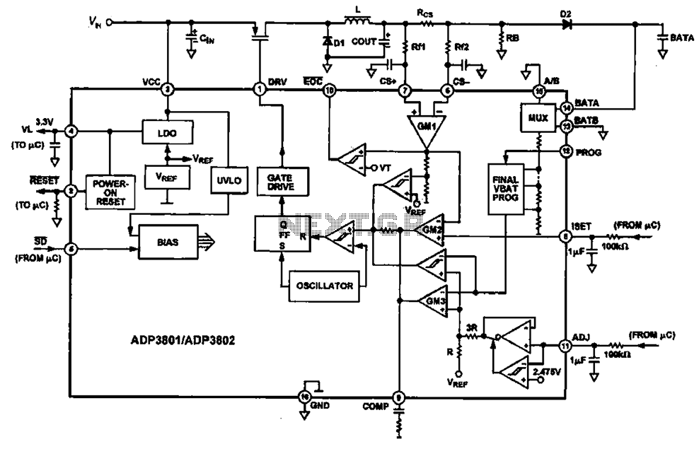
Charging circuit diagram for personal work based on the operating principle of ADP3801/3802 charging circuit. The ADP3801/3802 is a highly integrated battery charger controller designed for Li-ion and Li-polymer batteries. The charging circuit typically consists of several key components including...
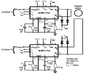
The schematic below represents a typical stepper motor driver application utilizing the NJM3770A. As illustrated in the diagram, the single-channel stepper motor drivers NJM3717 and NJM3770A operate independently and are not synchronized. The circuit design features the NJM3770A, a dedicated...
The Magnitude Comparator is a device that compares two 4-bit binary inputs to determine their relationship, indicating whether one input is greater than, equal to, or less than the other. It outputs the conditions A > B, A =...