
Magic Lights
The circuit design is centered around the use of bi-color LEDs, which are capable of producing multiple colors based on the applied voltage to their terminals. The common cathode configuration simplifies the control of the LEDs, as the ground connection is shared among all units. The 555 timer IC, configured in astable mode, generates a continuous square wave output that serves as a clock signal. This clock signal drives the dual BCD counters (CD4518), allowing for sequential counting and output generation.
The cascading of the two CD4518 counters expands the number of outputs available for controlling the LEDs, effectively doubling the output from four to eight per counter. Each output is connected to BCD to 7-segment latch/decoder/driver ICs (IC4 through IC7), which convert the binary-coded decimal outputs from the counters into signals suitable for controlling the LEDs. The arrangement of these components ensures that the LED outputs are synchronized with the clock signal, creating dynamic lighting patterns.
The current-limiting resistors are crucial for protecting the LEDs from excessive current, which can lead to damage. The careful selection of resistor values is necessary to ensure that the LEDs operate within their specified current ratings while achieving the desired brightness.
Overall, this circuit is well-suited for decorative lighting applications, providing an engaging visual display through the interplay of colors generated by the bi-color LEDs. The combination of the 555 timer, BCD counters, and decoder/driver ICs facilitates a versatile and effective means of creating animated lighting effects.The circuit as shown in the figure employs 14 bi-colour (red and green) LEDs having three terminals each. Different dancing colour patterns are produced using this circuit since each LED can produce three different colours.
The middle terminal (pin 2) of the LEDs is the common cathode pin which is grounded. When a positive voltage is applied to pi n 1, it emits red light. Similarly, when positive voltage is applied to pin 3. it emits green light. And when positive voltage is simultaneously applied to its pins 1 and 3, it emits amber light. The circuit can be used for decorative lights. IC1 (555) is used in astable mode to generate clock signal for IC2 and IC3 (CD4518) which are dual BCD counters. Both counters of each of these ICs have been cascaded to obtain 8 outputs from each. The outputs from IC2 and IC3 are connected to IC4 through IC7 which are BCD to 7-segment latch/decodor/driver ICs.
Thus we obtain a total of 14 segment outputs from each of the IC pairs consisting of IC4 plus IC5 and IC6 plus IC7. While outputs from former pair are connected to pin No. 1 of all the 14 bi-colour LEDs via current limiting resistors, the ouputs of the latter pair are similarly connected to pin No.
3 of all the bi-colour LEDs to get a magical dancing lights effect. 🔗 External reference
Related Circuits
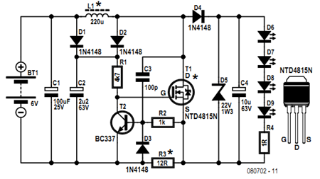
Before getting started, an acknowledgment is due. The circuit presented here employs an innovative method of controlling a flyback converter using the voltage developed across a current-sensing resistor. This approach was published by Andrew Armstrong in the July 1992...
This project involves outdoor LED solar garden lights, which function as an automatic garden lighting system utilizing a light-dependent resistor (LDR) and a 6V/5W solar panel. During daylight hours, the internal rechargeable 6 Volt sealed lead-acid (SLA) battery is...
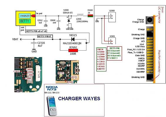
The display lights issue on the Nokia N73 can arise from various factors, such as a broken path in the display circuit or damage to the display driver, among others. This mobile repair guide offers pictures related to the...
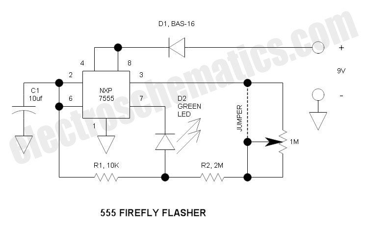
This circuit differs from the standard 555 oscillator circuit by placing the LED in the capacitor reset line (pin 7). This configuration reduces overall current and prevents high peak LED current from draining the battery. The forward voltage drop...
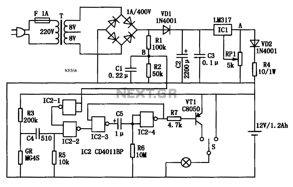
An automatic multipurpose emergency lights circuit is presented. Typically, emergency lights are connected to the mains for standby when fully charged. In the event of a sudden power failure, the ambient light transitions from strong to weak, indicating a...
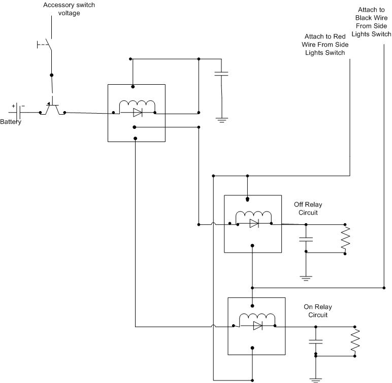
A decision has been made to install daytime driving lights for an Elise vehicle. The intention is to eliminate the need for manually pressing the button on and off repeatedly. The installation of daytime driving lights (DRLs) enhances vehicle visibility...